Air To Water Scroll Heat Pump Mechanical Layout With 6 Inch Piping

Ratings & Reviews
Be the first to share your experience with this product. Your review helps others make better decisions!
Description
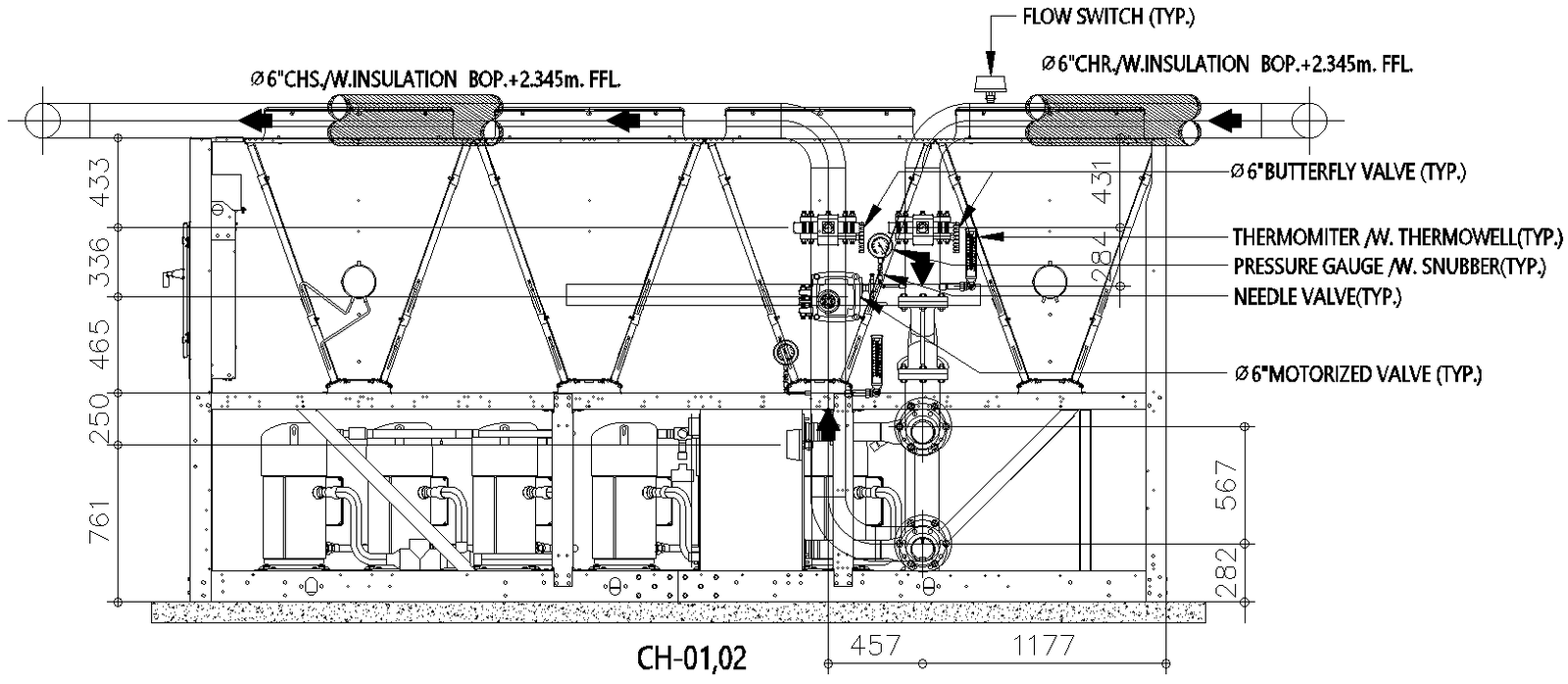
This AutoCAD DWG drawing shows a detailed air-to-water scroll heat pump machinery layout prepared for HVAC and MEP coordination. The drawing clearly illustrates the complete heat pump assembly with compressors, heat exchanger coils, structural frame, and base support. Pipe routing is shown with 6-inch CHS lines, including insulation marked at the bottom of the pipe plus 2345 mm from finished floor level. Valve components such as butterfly valves, motorized valves, needle valves, flow switches, pressure gauges with snubbers, and thermometers with thermowells are accurately positioned and labeled. Dimensional details, including overall unit height of approximately 1800 mm, base offsets, pipe center distances, and clearance zones, are clearly indicated for installation accuracy.
The DWG file also provides foundation and inertia base details, equipment spacing, and service access allowances required for maintenance and operation. Connection points, flow direction arrows, and component elevations support effective integration into HVAC plant rooms and mechanical layouts. This AutoCAD DWG file is suitable for architects, mechanical engineers, MEP consultants, and contractors who require precise air-to-water scroll heat pump drawings with measurements, valve details, and piping coordination for efficient HVAC system planning and execution.
File Type:
DWG
File Size:
1.4 MB
Category::
Mechanical and Machinery
Sub Category::
Mechanical Engineering
type:
Gold
Tags
Uploaded by:
Eiz
Luna
Ratings & Reviews
Be the first to share your experience with this product. Your review helps others make better decisions!