Chemical Reactor Layout Drawing With Plan Elevation And Section
Description
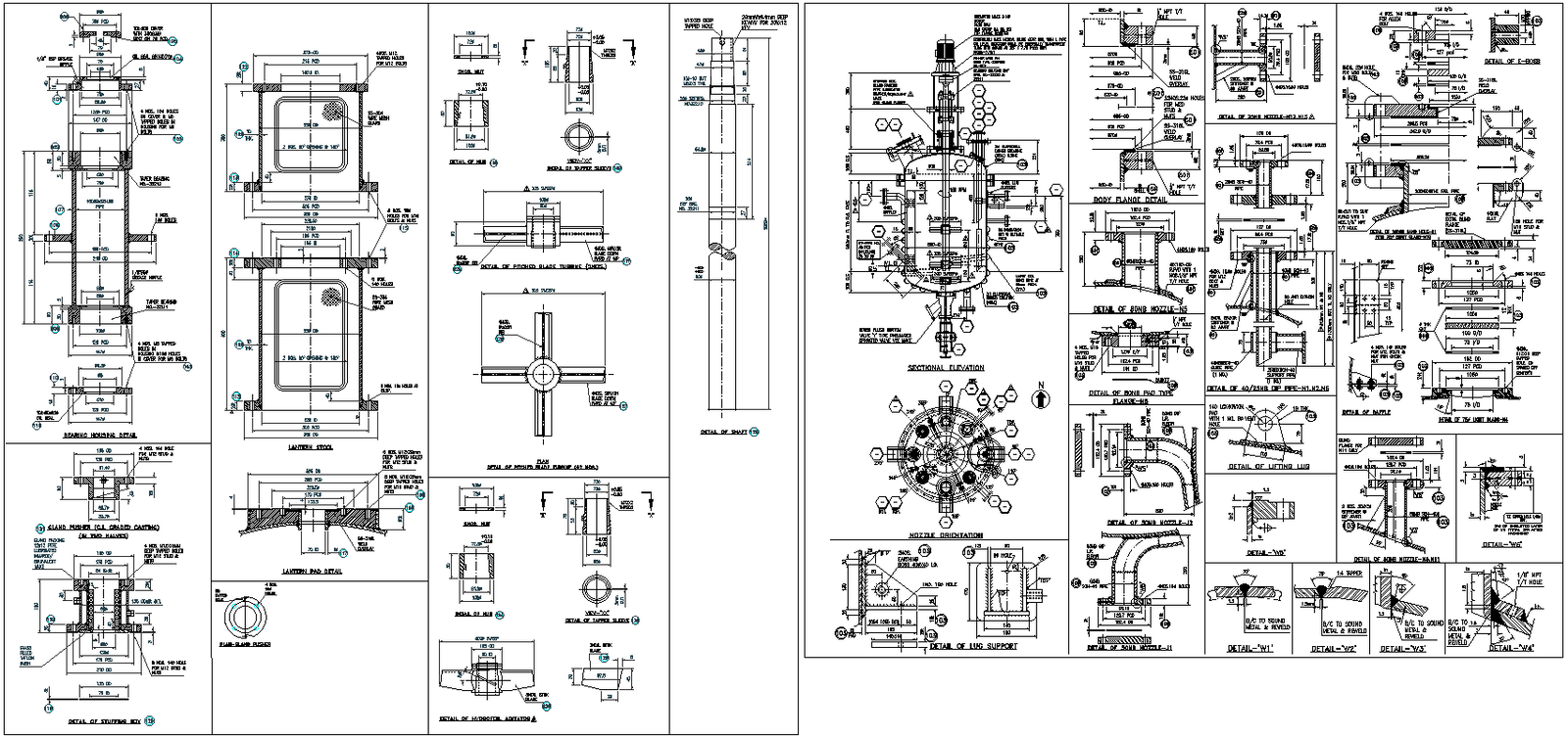
This AutoCAD DWG drawing provides a comprehensive chemical reactor layout with detailed plans, elevations, and sectional views prepared for industrial and process engineering applications. The drawing illustrates a vertical chemical reactor vessel with clearly defined shell diameter, nozzle locations, flange connections, internal supports, and base arrangements. Detailed sectional views show internal components such as agitator shaft alignment, baffle positions, inlet and outlet nozzles, manhole access, and reinforcement details. Precise dimensions, thickness notations, bolt patterns, and fabrication tolerances are clearly marked, making the drawing suitable for design verification, manufacturing reference, and construction coordination.
The DWG file also includes enlarged component details such as nozzle connections, support brackets, curved pipe bends, flange joints, and welded assemblies with accurate measurements. Orientation views and reference markers help in understanding spatial arrangement and installation sequencing. This chemical reactor drawing AutoCAD file is ideal for chemical engineers, mechanical engineers, plant designers, and consultants who require accurate reactor design documentation. The file supports equipment detailing, layout planning, and coordination with process piping and structural systems, ensuring clarity and precision during the execution of chemical plant and industrial projects.
File Type:
DWG
File Size:
2 MB
Category::
Mechanical and Machinery
Sub Category::
Mechanical Engineering
type:
Gold

Uploaded by:
Eiz
Luna