Piping Connection Layout with NPD Sizes Angles and Lengths DWG
Description
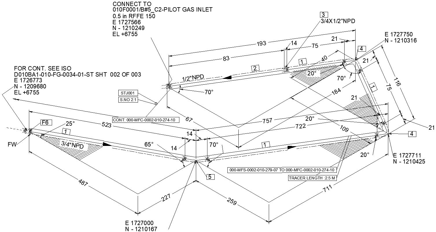
This piping connection layout CAD DWG drawing provides a precise construction level representation of an industrial piping system with clearly defined dimensions, angles, and connection references. The drawing shows detailed routing of 1/2 NPD and 3/4 NPD pipelines with accurate center line lengths such as 193 mm, 487 mm, 523 mm, 711 mm, 722 mm, and 757 mm, ensuring correct fabrication and installation. Angular changes, including 20-degree, 25-degree, 65-degree, and 70-degree bends, are illustrated to explain directional flow and alignment. Each connection point is marked with coordinates, elevations, and reference tags to support exact positioning during site execution. Flow direction arrows, weld locations, and fitting transitions are clearly indicated for proper construction understanding.
This piping construction layout drawing is useful for planning new piping installations as well as modifying existing systems with confidence. The DWG file helps engineers and designers visualize pipe routing, spacing, and geometry while reducing errors during execution. Tracer length details, joint identification, and connection continuity are included to support installation accuracy and inspection requirements. The scalable CAD format allows clear review of measurements, bend orientations, and connection points at different zoom levels. Overall, this piping connection DWG drawing serves as a reliable technical reference for accurate coordination, construction planning, and efficient execution of piping works in industrial projects.

Uploaded by:
Eiz
Luna
