Electrical Layout Design for Control Room DWG with Dimensions
Description
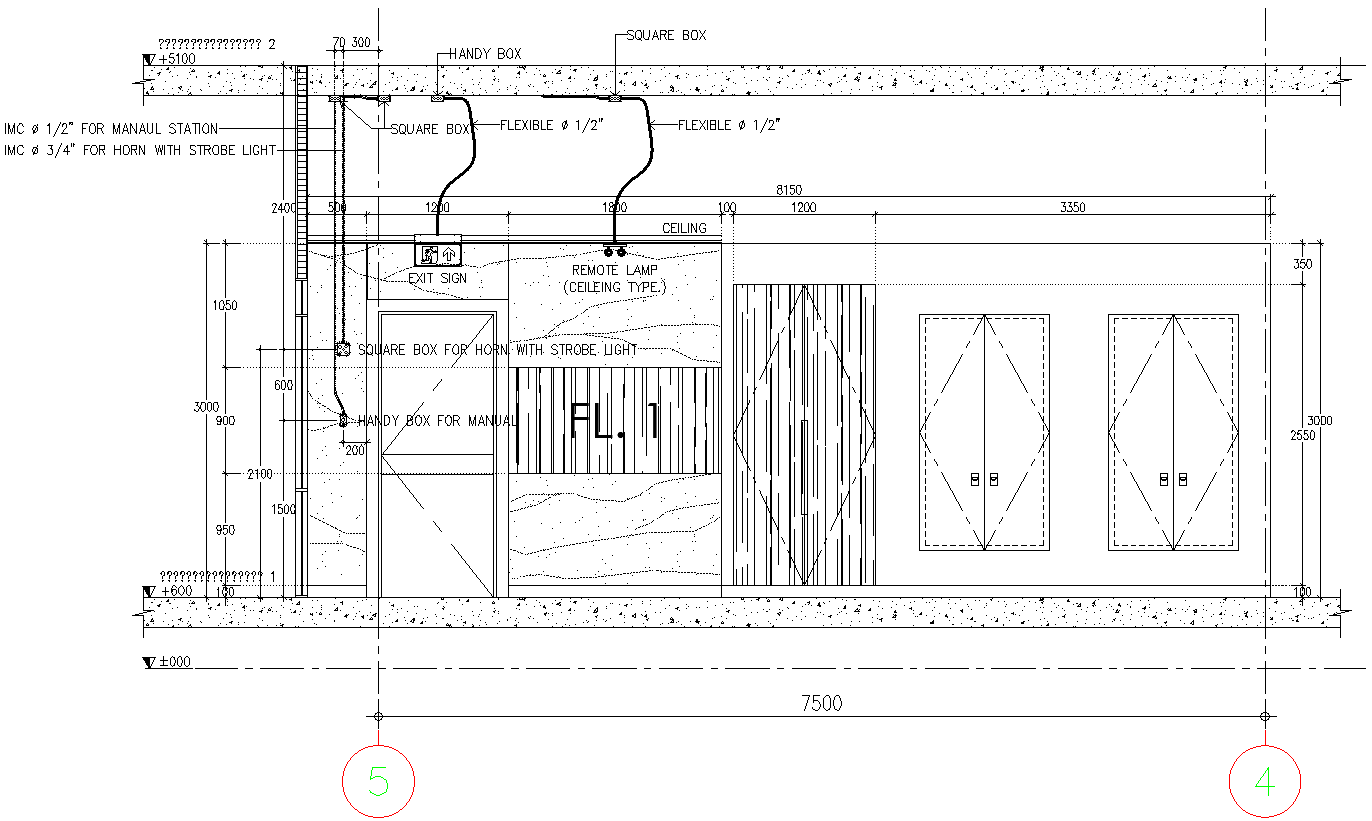
This AutoCAD DWG file presents a detailed electrical layout design for a control room, prepared with clear dimensions and equipment positioning. The drawing includes accurate placement of electrical components such as handy boxes, square boxes, flexible conduits, manual stations, exit sign wiring, remote ceiling lamps, and a horn with strobe light connections. Conduit routing is shown using IMC sizes, including 1 2 inch for manual stations and 3 4 inch for horn and strobe systems. Ceiling level markings, floor level references, and wall-mounted electrical points are clearly indicated to support precise installation. The layout also shows vertical and horizontal conduit paths with proper spacing, junction box locations, and mounting heights for control room safety and operational requirements. Measurement details such as overall width, height clearances, and equipment offsets are included to ensure accuracy during execution. This electrical drawing is suitable for control rooms in industrial, utility, or commercial buildings where structured electrical planning is required. The DWG file serves as a reliable reference for architects, electrical engineers, and technical consultants involved in control room electrical system design and coordination.
File Type:
DWG
File Size:
559 KB
Category::
Electrical
Sub Category::
Architecture Electrical Plans
type:
Gold

Uploaded by:
Eiz
Luna
