Butterfly Valve Sectional Design Details for Industrial Piping Systems
Description
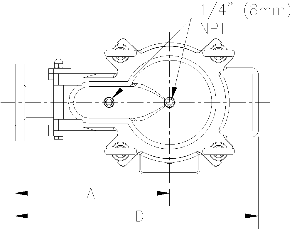
This AutoCAD drawing presents detailed butterfly valve sectional design details developed for piping layouts used in Industrial Plant and Mechanical and Machinery applications. The sectional view clearly explains the internal valve components, including disc position, shaft alignment, valve body profile, sealing area, and connection ends. Centerlines and sectional cuts are applied to explain valve operation and flow control behavior. Dimensional references such as bore diameter, valve depth, and connection spacing are accurately indicated to support installation and coordination within pipeline systems. The drawing follows professional Construction Detail Drawings standards for clarity and technical accuracy.
The layout also includes material references, fixing locations, and mechanical annotations commonly required for industrial documentation. Sectional clarity supports proper understanding of valve placement within piping networks and equipment layouts. This butterfly valve sectional drawing is suitable for engineers, designers, and project teams involved in industrial piping and machinery coordination. Clean drafting, balanced proportions, and structured detailing make this drawing reliable for fabrication reference, installation planning, and system coordination using AutoCAD-based industrial design workflows.
File Type:
DWG
File Size:
144 KB
Category::
Electrical
Sub Category::
Architecture Electrical Plans
type:
Gold

Uploaded by:
Eiz
Luna
