Typical Duct Tray Trunking and Pipe Section Layout Plan Details
Description
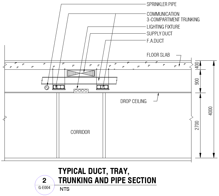
This AutoCAD drawing presents a detailed, typical duct, tray, trunking, and pipe section layout prepared for coordinated service planning in buildings. The section clearly illustrates the vertical and horizontal arrangement of HVAC ducts, cable trays, communication trunking, sprinkler pipes, and supply ducts below the floor slab. Dimensioned clearances such as slab thickness, drop ceiling depth, and corridor height are accurately shown to support proper coordination. Each service element is labeled to explain routing, spacing, and alignment within the ceiling zone, making the drawing suitable for construction-level execution.
The layout also supports Electrical and service coordination by showing cable tray placement, trunking segregation, and relationship with mechanical ducts and piping. Clear section labeling and structured linework help users understand how multiple services integrate without conflict. This section drawing is useful for Projects where precise service coordination and ceiling space management are required. Clean drafting and consistent proportions improve clarity during planning and site implementation. The drawing also aligns with Structure Drawing requirements by maintaining correct slab references and vertical dimensions for coordinated execution using AutoCAD-based workflows.

Uploaded by:
Eiz
Luna
