Unifilar Electrical Transfer Protection Layout Design Diagram
Tags
Ratings & Reviews
Be the first to share your experience with this product. Your review helps others make better decisions!
Description
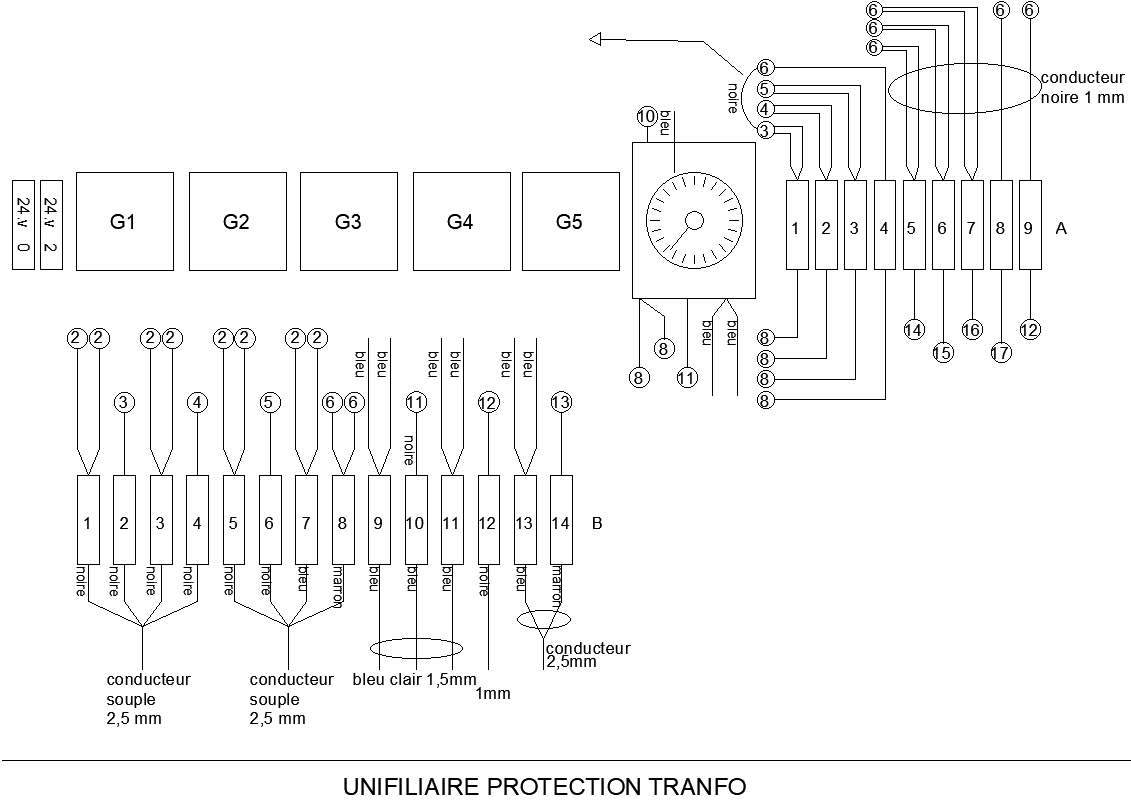
This AutoCAD drawing presents a detailed unifilar electrical transfer layout design prepared for Electrical system planning and protection coordination. The unifilar diagram clearly illustrates power flow paths, protection transfer logic, and component interconnections using a simplified single-line representation. Elements such as generators, protection relays, control terminals, conductors, and circuit numbering are clearly shown to explain system operation. Wire sizes, connection points, and signal directions are carefully indicated to support correct interpretation of the protection transfer process. The drawing helps users understand how electrical continuity and safety are maintained during transfer conditions.
The layout also supports Structure coordination by showing clear alignment of electrical components within the system framework. Clean annotations and organized grouping improve readability for installation and verification tasks. This unifilar electrical layout drawing is useful for professionals working on Electrical Machine systems and power-related Projects where protection transfer documentation is required. Accurate drafting, balanced proportions, and standard electrical symbols make the drawing reliable for planning, execution, and maintenance using AutoCAD-based electrical design workflows.

Uploaded by:
Eiz Luna
Tags
Ratings & Reviews
Be the first to share your experience with this product. Your review helps others make better decisions!