Electrical Schematic Control Panel Wiring Diagram Layout Plan
Tags
Ratings & Reviews
Be the first to share your experience with this product. Your review helps others make better decisions!
Description
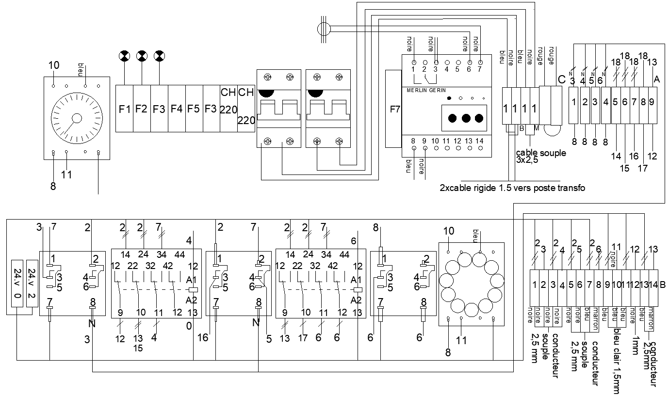
This AutoCAD drawing presents a detailed electrical schematic, showing a plan for control panel wiring used in Electrical system planning. The schematic clearly illustrates the interconnection of control components such as circuit breakers, relays, transformers, terminal blocks, switches, and power supply units. Wiring paths are drawn with clear numbering and symbols to explain control logic and power distribution. The layout helps users understand how individual components interact within the panel for safe and efficient operation. The drawing is drafted using standard DWG CAD Blocks, ensuring clarity, consistency, and professional presentation.
The schematic also supports installation and troubleshooting tasks by clearly defining wiring terminals, conductor routing, and control sequencing. Component labeling and organized circuit grouping improve readability during maintenance and system verification. This electrical schematic drawing is suitable for professionals working on Electrical Machine systems and automation-related Projects. Clean drafting, structured layout, and accurate symbol usage make this drawing reliable for panel planning, execution, and documentation using AutoCAD-based electrical workflows.

Uploaded by:
Eiz Luna
Tags
Ratings & Reviews
Be the first to share your experience with this product. Your review helps others make better decisions!