Transformer Protection Command Circuit Diagram with Control Logic
Tags
Ratings & Reviews
Be the first to share your experience with this product. Your review helps others make better decisions!
Description
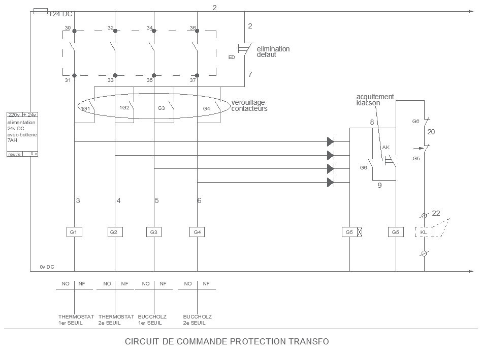
This AutoCAD drawing shows a detailed transformer protection command circuit diagram prepared for Electrical system planning in power installations. The diagram clearly explains command logic using control supply lines, relays, contactors, alarm circuits, and interlocking arrangements. Components such as thermostats, Buchholz relay contacts, fault elimination paths, and locking contactors are shown with standard symbols and clear line references. Terminal numbering and circuit flow direction help users understand how the protection system responds during normal operation and fault conditions. The drawing is structured using professional DWG CAD Blocks to ensure clarity and technical accuracy.
The layout also supports construction-level execution by clearly defining alarm and trip command logic for transformer safety. Clean annotations and organized wiring paths allow easy verification during installation and maintenance. This transformer command circuit drawing is useful for engineers and technicians working on power-related Projects where transformer protection documentation is required. Accurate logic representation and clear drafting improve safety, coordination, and system reliability in electrical installations using AutoCAD-based workflows.

Uploaded by:
Eiz Luna
Tags
Ratings & Reviews
Be the first to share your experience with this product. Your review helps others make better decisions!