Down Conductor Section Detail Layout for Lightning Protection
Description
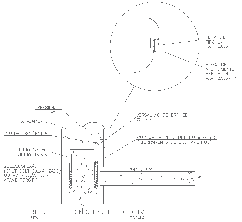
This AutoCAD drawing illustrates a detailed conductor section detail layout used in electrical lightning protection and grounding systems for modern construction projects. The drawing clearly shows the vertical down conductor arrangement connected from the structure to the earthing system. Key elements such as conductor routing, fixing method, and connection points are accurately represented. Materials, including copper conductor, bronze rod, grounding plate, and exothermic welding connections, are shown with proper annotations. Structural components like concrete cover, slab, pillar, and reinforcement are included to explain how the down conductor integrates with the building structure using professional DWG CAD blocks standards.
The layout also highlights installation details such as conductor size, fixing brackets, welding joints, and grounding continuity to ensure electrical safety and compliance. Clear symbols, notes, and dimensional references help engineers and designers understand correct placement and construction practice. This electrical down-conductor detail drawing is suitable for residential, commercial, and industrial construction projects. With clean drafting, accurate scaling, and technical clarity, the drawing supports reliable grounding design, system safety, and execution using AutoCAD-based electrical DWG CAD blocks workflows.
File Type:
DWG
File Size:
1020 KB
Category::
Electrical
Sub Category::
Architecture Electrical Plans
type:
Gold

Uploaded by:
Eiz
Luna