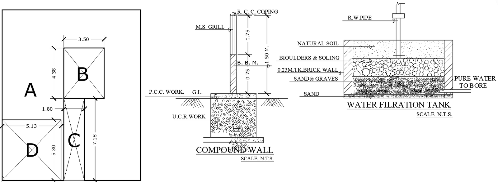
Water Filtration Tank DWG with 1.50 m Wall and 0.75 m Coping
Tags
Ratings & Reviews
Be the first to share your experience with this product. Your review helps others make better decisions!
Description
This AutoCAD DWG file features a complete water filtration tank and compound wall layout, illustrating essential dimensions, material layers, and construction details required for civil and architectural projects. The filtration tank drawing shows multiple strata, including sand, sand and gravel, boulders, and soil, and a 0.23 m thick brick wall used to create the filtration chamber. Clear annotations highlight the natural soil, outlet for pure water to the bore, and the R.W. pipe connection. The cross-section displays the filtration sequence, ensuring proper water flow and purification efficiency. Each layer is drafted with detailing that supports accurate execution in water treatment and site planning.
The compound wall drawing presents a structured section with 0.75 m R.C.C. coping, 1.50 m M.S. grill, and 0.75 m B.B.M. masonry, supported by P.C.C. work at ground level and U.C.R. work below. The wall footing is represented with a stable base, enabling durability and load resistance. Dimensioned blocks labeled A, B, C, and D with respective measurements such as 3.50 m, 4.38 m, 5.13 m, 5.30 m, and 7.18 m provide clarity on proportions and alignment. This DWG is ideal for engineers and designers needing precise compound wall and water filtration tank drawings for site development, utility planning, and construction detailing.

Uploaded by:
Eiz Luna
Tags
Ratings & Reviews
Be the first to share your experience with this product. Your review helps others make better decisions!