Structural Layout of Column and Footing Plan AutoCAD DWG Drawing
Description
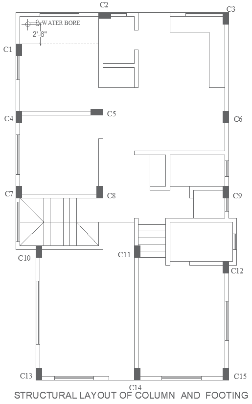
This AutoCAD DWG drawing presents a detailed structural layout plan of columns and footings designed for accurate building construction. The layout clearly marks column positions from C1 to C15, ensuring proper structural grid alignment and load distribution across the building footprint. Each column location is precisely drafted with uniform spacing and clear references, supporting efficient coordination between architectural and structural drawings. The plan also includes footing placement details aligned with column positions, helping engineers understand foundation support requirements. A labeled water bore location with dimensions is shown, allowing early-stage coordination of utilities without affecting structural integrity. Clean linework, standard symbols, and accurate proportions make this drawing suitable for professional use in planning and execution stages.
The column and footing layout supports both residential and commercial construction projects by providing a reliable base for foundation design and structural stability. Staircase and circulation zones are clearly integrated within the column grid, helping avoid conflicts during construction. The drawing assists architects, civil engineers, and builders in preparing construction documents, site execution plans, and approval drawings. With clearly defined structural elements and logical layout organization, this DWG file helps reduce on-site errors, improves coordination, and supports efficient construction workflows while maintaining structural accuracy and consistency throughout the project.

Uploaded by:
Eiz
Luna
