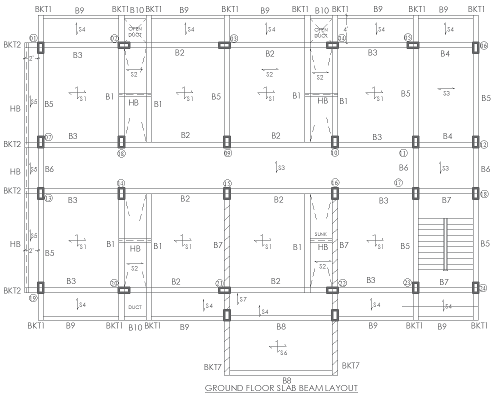
Ground Floor Slab Beam Layouts DWG with BKT B1 B2 B3 Details
Tags
Ratings & Reviews
Be the first to share your experience with this product. Your review helps others make better decisions!
Description
This AutoCAD DWG file presents a precise and detailed Ground Floor Slab Beam Layout designed for accurate structural planning. The drawing includes all major beam identifiers such as B1, B2, B3, B4, B5, B6, B7, B8, and B9, along with bracket supports BKT1, BKT,2 and BKT7 placed across the grid for stability. Slab directions S1, S2, S3,3, and S4 are clearly marked to guide reinforcement flow and load transfer. The file also shows HB markers, sunk areas, duct openings, and grid points 01 to 24, allowing engineers to review service routes and structural junctions. Each beam junction and slab division is represented with precise alignment to ensure proper material estimation and construction coordination.
This drawing is ideal for architects, civil engineers, interior planners, and structural designers who require a dependable layout for ground floor reinforcement and beam positioning. The DWG plan supports clear visualization of structural continuity, helping users understand slab distribution and column interaction throughout the design. With exact directional arrows, spacing, and coordinated section references, this ground floor layout enhances workflow accuracy and reduces design errors. It is especially useful for residential and commercial building projects where precise beam placement and slab performance are crucial for long-term structural strength.

Uploaded by:
Eiz Luna
Tags
Ratings & Reviews
Be the first to share your experience with this product. Your review helps others make better decisions!