Underground Water Supply Foundation DWG with Section and Plan
Description
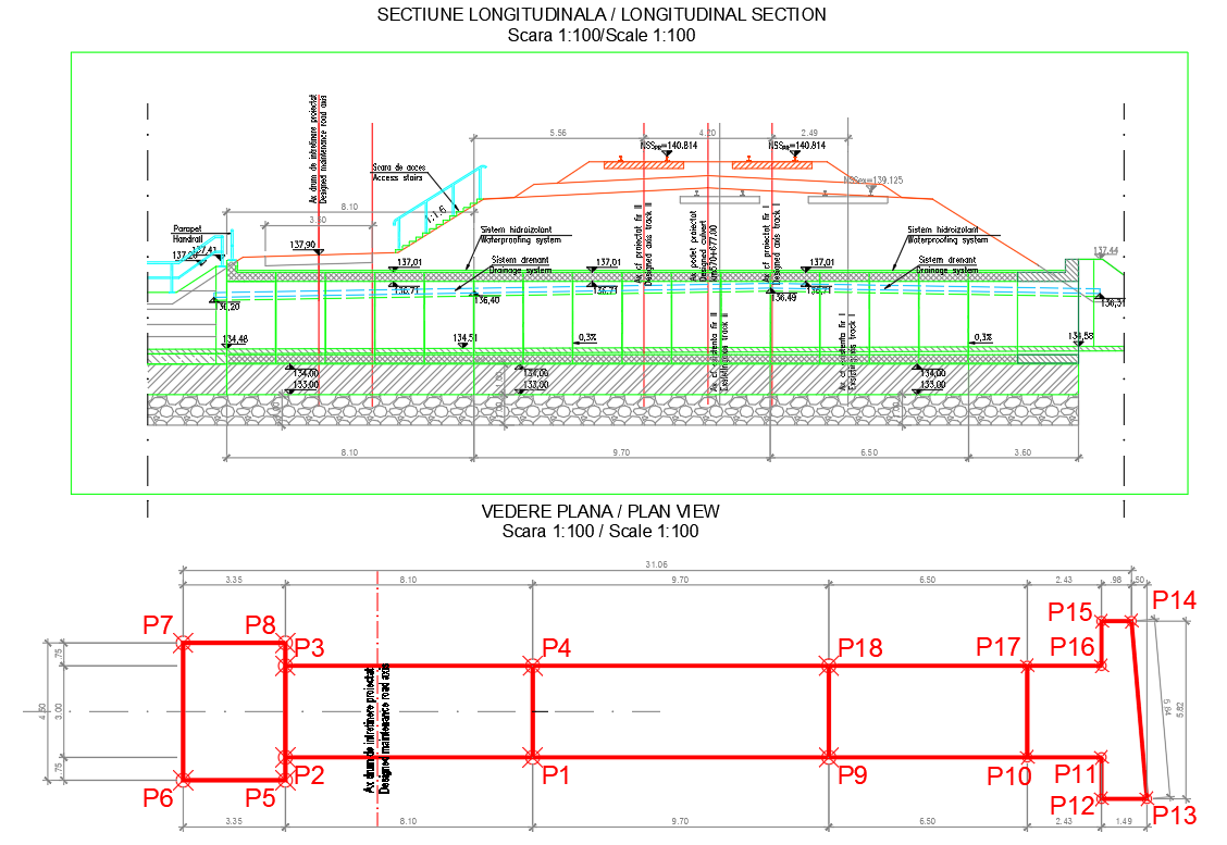
This Underground Water Supply System Foundation DWG Drawing provides a complete technical layout featuring longitudinal sections and plan views at a 1:100 scale. The longitudinal section shows detailed elevation levels such as 137.01, 134.56, and 135.00, along with slope indications of 0.3 percent for controlled water flow. Waterproofing system layers, drainage channels, protective coatings, gravel foundation beds, and structural slab thicknesses are clearly marked. Pipe routes, access shafts, and support structures are illustrated with precise spacing, ensuring accurate installation and long-term stability for water distribution networks.
The plan view highlights node points P1 to P18, with dimensions like 8.10 m, 9.70 m, 6.50 m, and 3.35 m identified for proper alignment of the underground system. Red-marked structural axes guide foundation positioning, while internal spacing and boundary offsets help engineers coordinate excavation and reinforcement. This DWG drawing is ideal for civil engineers, project planners, and construction teams who require accurate underground water supply foundation details for infrastructure projects. The combination of section cuts, plan dimensions, and material references supports efficient planning, structural safety, and reliable system performance.
Uploaded by:
manveen
kaur