Typical Beam Reinforcement Detail Drawing in AutoCAD DWG Format
Description
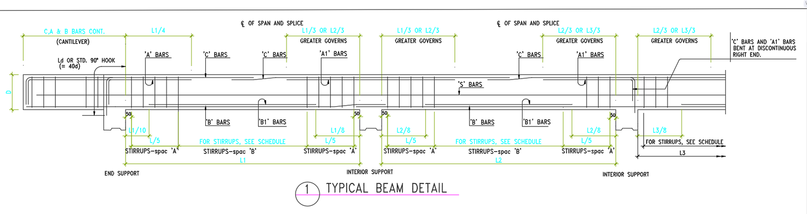
This AutoCAD DWG file provides a detailed typical beam reinforcement layout, illustrating the complete arrangement of A bars, B bars, C bars, A1 bars, B1 bars, and S bars along with accurate placement lengths such as L1, L2, and L3. The drawing shows the reinforcement distribution at end supports, interior supports, and mid spans following standard structural design requirements. Clear annotations define development lengths, standard hooks, splice zones, and bar continuation requirements. The drawing also highlights L1 by 4, L1 by 5, L2 by 8, and L3 by 8 reinforcement lengths, ensuring precise bar positioning.
In addition, the DWG file includes stirrup spacing types A and B, with instructions directing users to the stirrup schedule for complete spacing references. Beam depth dimension D, cantilever reinforcement continuation, and support zone bar detailing are presented with clarity for easy interpretation. This typical beam detail is ideal for architects, structural engineers, and contractors who require accurate reinforcement drawings for RCC beam construction. Every line, label, and measurement is drafted to support reliable execution on-site, making this file a valuable reference for residential, commercial, and high-rise building projects.
Uploaded by:
manveen
kaur
