High Raised Building Footing and Section A-A Detail DWG Drawing
Description
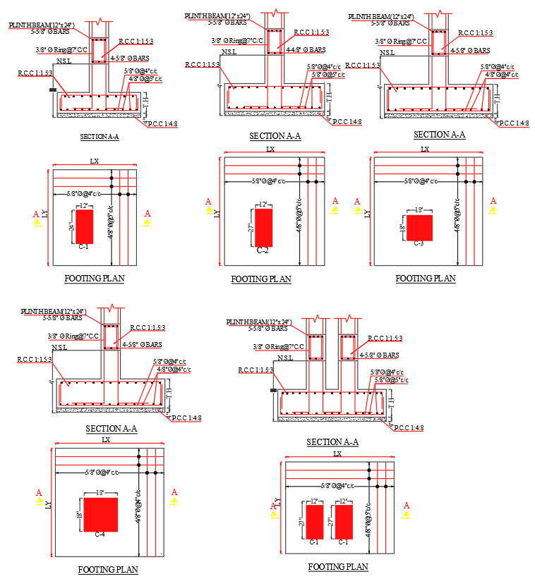
This AutoCAD DWG drawing provides a complete set of high-raised building footing details, showing clear footing plans, reinforcement layouts, and Section A-A construction specifications. The design includes footing sizes such as C-1 (1'×2'), C-2 (1'×2'), C-3 (1'8"×2'), and C-4 (1'×2'), with reinforcement arrangements including 5/8" Ø bars @ 4" c/c, 3/8" Ø rings @ 7" c/c, and 4–5/8" Ø main bars. The plinth beam dimensions of 12"×24" are also clearly included, ensuring accurate alignment between footing, column, and beam placement. Each footing layout is supported with centreline markings, column positioning, and required RCC and PCC layers.
The sectional details show reinforcement distribution from foundation level to plinth level, indicating bar spacing, cover thickness, and NSL reference levels. The drawing highlights the proper arrangement of longitudinal and transverse reinforcement, concrete grades, and anchorage lengths for stable footing performance in high-rise structures. This DWG file is ideal for architects, structural engineers, and construction professionals who require accurate footing reinforcement drawings for residential or commercial high-rise projects. The precise detailing and structured layout help ensure correct site execution and improve the reliability of foundation construction.
Uploaded by:
manveen
kaur