Split AC Installation and Piping Layout in DWG CAD Drawing File
Description
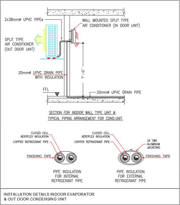
This detailed CAD drawing presents the complete installation layout for a split AC system, categorized under HVAC Layout and Mechanical Services Drawing due to its comprehensive technical detailing. The plan illustrates the indoor wall-mounted evaporator unit and the outdoor condensing unit with accurate piping routes and insulation specifications. Key measurements such as 7-0 ft mounting height, 2×38 mm UPVC refrigerant pipes, and 20 mm insulated UPVC drain pipe are clearly represented. The section view shows wall penetration points, finishing tape usage, refrigerant pipe bends, and drain flow direction, ensuring proper understanding of the installation process. The drawing also highlights safe mounting positions and the transition from indoor to outdoor units for precise system setup.
Additional details include closed-cell Aeroflex insulation for internal and external copper refrigerant pipes, 26 SWG aluminum jacketing for outdoor protection, and multiple insulation layers designed to maintain system efficiency. The labeled refrigerant line arrangement and insulation finishes help installers manage routing with accuracy. This layout is ideal for HVAC engineers, AC technicians, and supervisors who require clear guidance for piping alignment, insulation application, and condensate drainage. With practical technical annotations and structured pipe detailing, this drawing supports reliable execution and long-term performance of split AC installations.
Uploaded by:
K.H.J
Jani
