High Rise Floor Plan DWG with Conduit Installation on Wood Board
Description
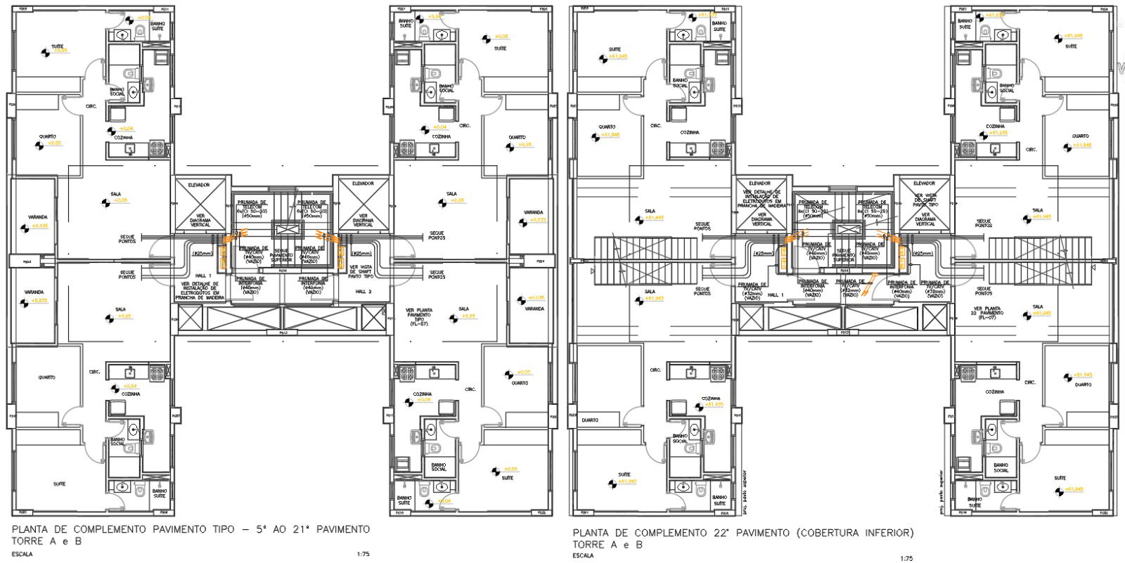
This AutoCAD DWG drawing presents a complete multi-storey residential floor plan combined with a detailed conduit installation layout mounted on wooden boards. The plan covers the typical 5th to 21st floors of Towers A and B, showing the arrangement of suites, bedrooms, kitchens, circulation spaces, verandas, and living areas with their respective measurements. The central core includes lift shafts, vertical ducts, hall widths, riser positions, and structural wall alignments, all marked with precise dimensions. Electrical points, switch locations, and ceiling fixture placements are clearly indicated across every unit to ensure accurate coordination during design review. The conduit lines are routed through designated shafts and service areas, making the electrical distribution path easy to follow throughout the building.
The 22nd floor plan expands on these details by introducing additional circulation connections, stair flight alignment, extended hall areas, and updated unit layouts. This section also highlights the wooden-board-mounted conduit paths, including bends, transitions, and cross-tower routing. Measurement labels throughout the plan help designers verify spacing, clearances, and core-to-unit distances. The drawing provides a comprehensive view of electrical service routing between both towers, offering a reliable reference for architects, engineers, MEP planners, and interior professionals working on high-rise residential developments.
File Type:
DWG
File Size:
607 KB
Category::
Electrical
Sub Category::
Electrical Automation Systems
type:
Gold

Uploaded by:
Eiz
Luna
