Floor Shaft Layout with Electroduct Installation Detail in DWG File
Description
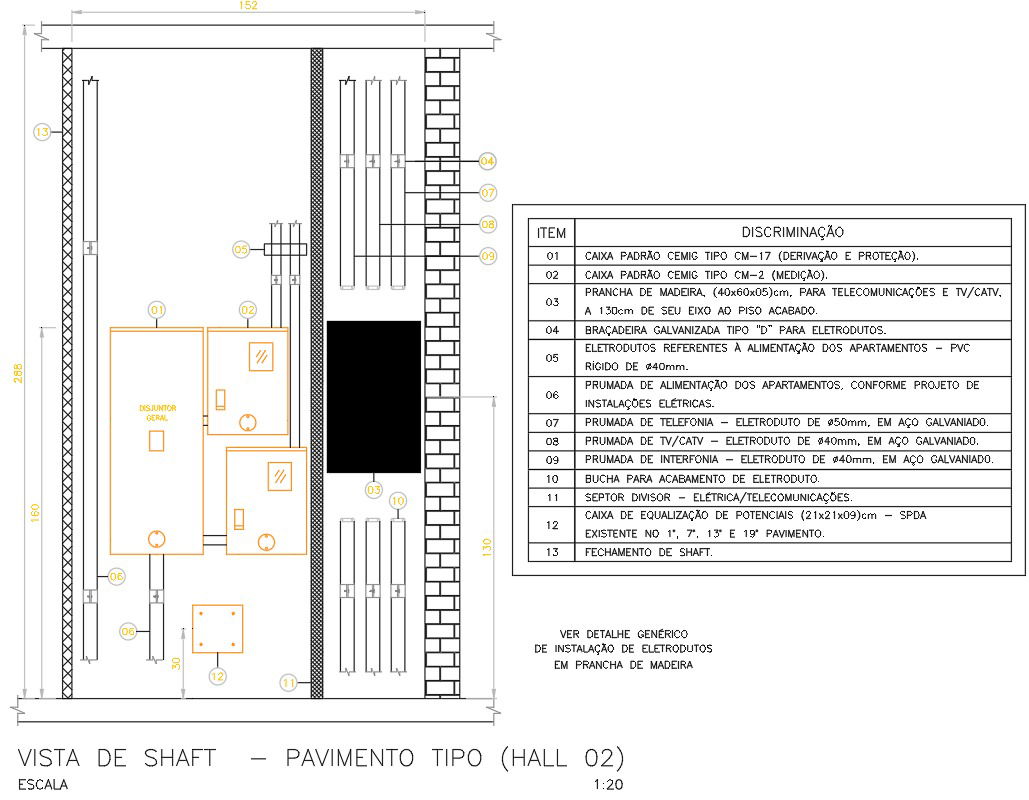
This detailed CAD drawing presents a complete shaft layout for a standard residential floor, showing the distribution of electrical and telecommunication systems with accurate measurements and installation notes. The design includes utility boxes such as CM17 for protection and CM2 for metering, positioned within a shaft width of 152 cm and an overall height of 298 cm. The drawing also highlights rigid PVC conduits for apartment power supply and galvanized steel conduits of Ø40 mm and Ø50 mm for TV, CATV, telephone, and intercom distribution. A wooden plank measuring 40 × 60 × 5 cm is installed 130 cm above the finished floor to support telecommunication equipment, secured using metallic brackets and bushings for conduit finishing. Each item in the layout corresponds to a detailed specification table for proper identification during site installation.
Additionally, the drawing illustrates horizontal and vertical routing paths, separation of telecom and electrical systems using divider panels, and a potential equalization box sized 12 × 12 × 109 cm located at key floors. The clear labeling and structured conduit arrangement ensure precise execution for multi-storey residential buildings. This shaft layout DWG is ideal for engineers, technicians, and designers who require a reliable reference for planning efficient service risers in building projects.
File Type:
DWG
File Size:
607 KB
Category::
Electrical
Sub Category::
Electrical Automation Systems
type:
Gold

Uploaded by:
Eiz
Luna
