Industrial PID Process Flow CAD Diagram with Valves and Pipelines
Description
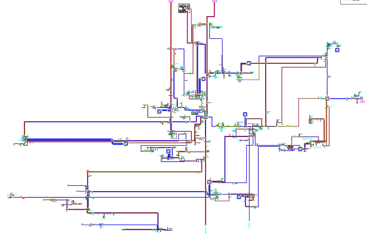
This Industrial Engineering and Process Design CAD layout presents a detailed P and ID diagram showing the complete process flow arrangement used in industrial plants and manufacturing systems. The drawing illustrates a complex network of pipelines, valves, pumps, junctions, and instrumentation devices marked using standard process symbols. Distinct colored lines represent different flow routes, helping users trace each path through control valves, pressure points, and monitoring devices. Branch lines, bypass routes, link connections, and directional arrows clearly define the interaction between various flow sections across the process network.
The diagram also highlights essential equipment such as pumps, flow meters, pressure indicators, temperature transmitters, and isolation valves that support smooth plant operation. Each component is labeled for quick identification, making this layout valuable for engineers involved in installation planning, system troubleshooting, and safety verification. This CAD drawing supports industrial automation teams, process engineers, and maintenance planners who require accurate documentation for system upgrades, process audits, and operational studies. With a clear structure and well-organized symbolic representation, the P and ID help ensure reliable coordination across all levels of industrial process design.

Uploaded by:
Eiz
Luna
