Typical Floor CAD Plan with Telecom and Intercom Shaft Layout
Description
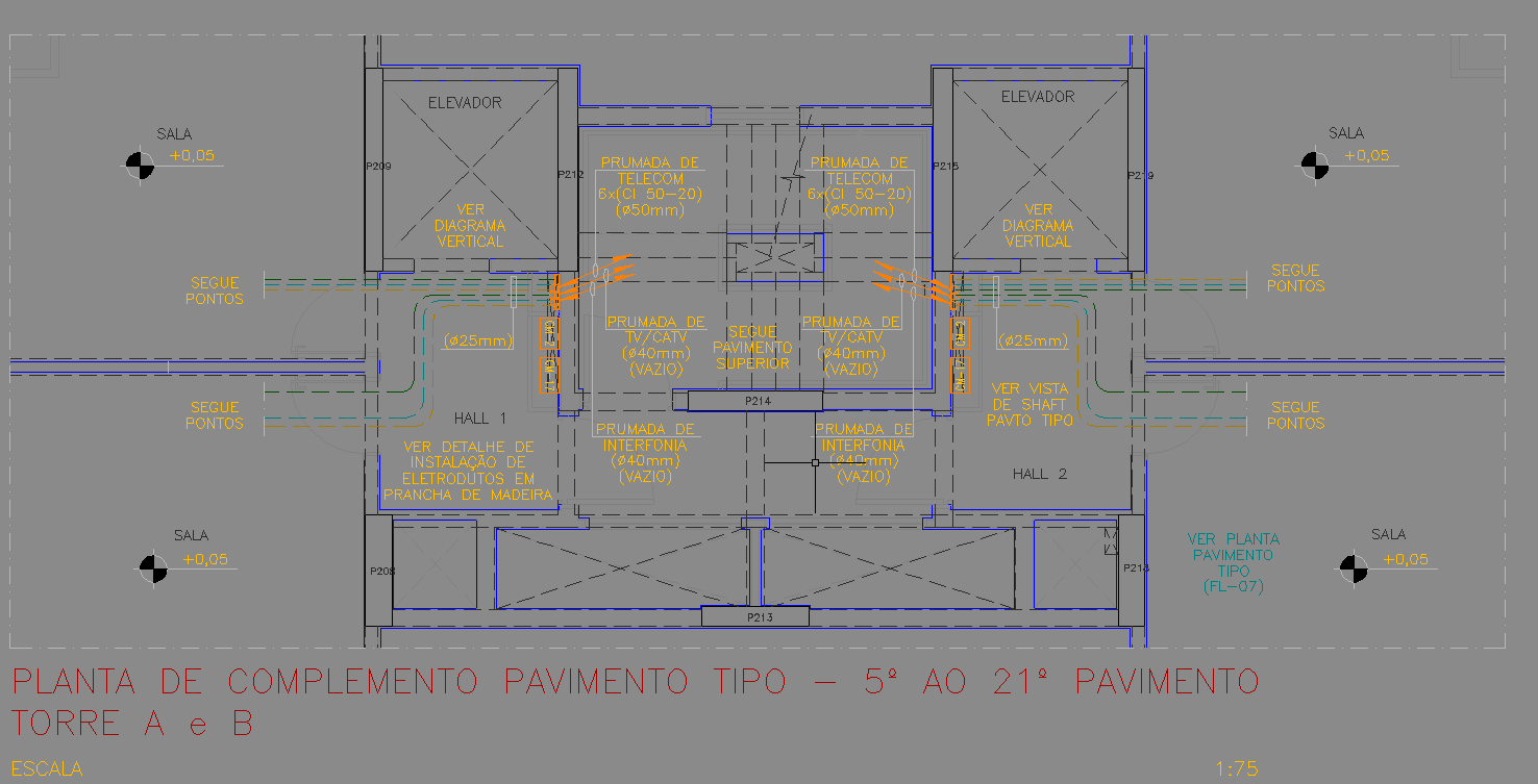
This AutoCAD DWG file presents a complete typical floor layout for a multi-tower residential or commercial building, covering levels from the 5th to the 21st floor. The plan highlights a central block containing elevators, service shafts, and corridor access zones for Tower A and Tower B. Each shaft includes labeled telecom risers, intercom conduits, TV/CATV ducts with Ø40 mm and Ø50 mm routing, and electrical pathways shown with color-coded lines. The drawing clearly marks multiple “segue pontos” indicating the continuation of service lines across floors. The routing of Ø25 mm conduits, wooden mounting boards for telecom installation, and upper-floor connection points are all displayed with precise dimensioning and annotation.
Additionally, the typical floor layout provides hall arrangements, shaft access zones, and alignment of vertical installations to ensure accurate stacking throughout all levels. The two elevator cores are fully represented with vertical diagram references, while service ducts are symmetrically placed between both towers for simplified coordination. This DWG file is ideal for MEP engineers, electrical planners, telecom designers, and project coordinators who need a clear understanding of repeated floor service distribution. With highly legible conduit routing, shaft labeling, and structural markers, the drawing supports clash detection, system integration, and detailed construction documentation.

Uploaded by:
Eiz
Luna