Utility Box Grounding System CAD Layout with 77x82 cm Details
Description
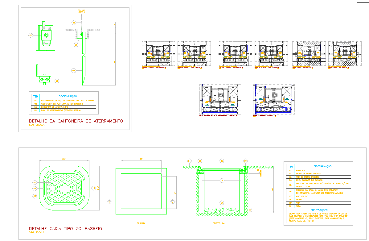
This AutoCAD DWG file presents a highly detailed utility box grounding system layout, showcasing the complete structural and electrical configuration required for safe field execution. The file includes precise measurements of the 77 cm by 82 cm ZC-type sidewalk utility box, top view and sectional view details, reinforcement distribution, base thickness, cover design, and concrete specifications. The grounding angle bracket assembly is also represented with exact component labels, showing the steel angle dimensions, bolt arrangement, copper connector placement, and the vertical grounding rod installation indicated in the drawing. Every element is annotated clearly, supporting accurate interpretation for design verification and project development.
Engineers, architects, and construction professionals can use this DWG drawing to ensure proper installation, alignment, and safety compliance in electrical and civil infrastructure projects. The file covers essential construction components such as the grille cover, pre-molded concrete parts, anchoring plates, and wiring access points, along with defined elevation levels and grid lines visible in the sections. This technical plan is especially useful for utility network planning, outdoor electrical box design, and grounding integration in urban pathways. With complete dimensional references and organized detailing, this CAD file provides a reliable resource for professional-grade execution and documentation.

Uploaded by:
john
kelly
