Industrial structural layout DWG with 48x32m plan and elevations
Description
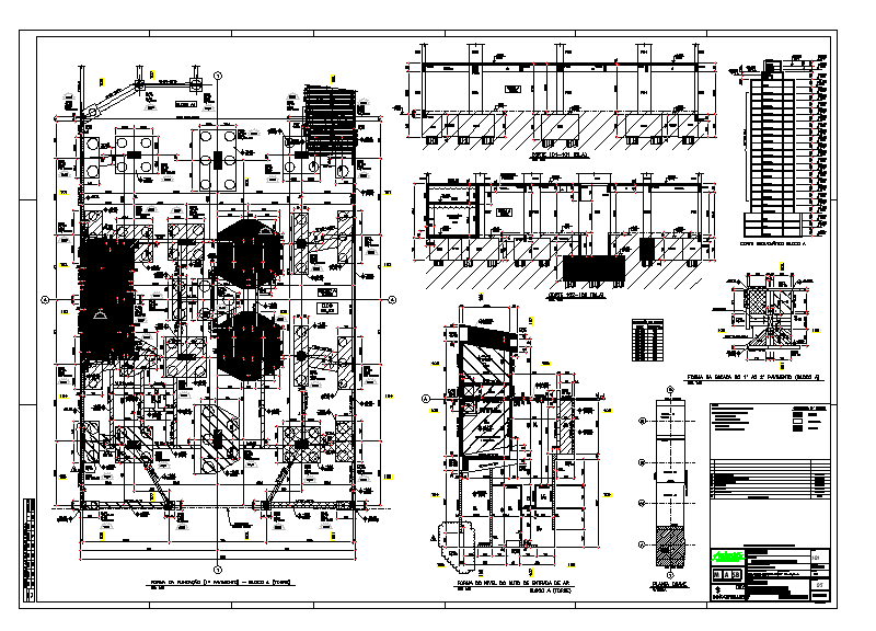
This AutoCAD DWG file presents a detailed 48 x 32 metre industrial structural layout, including complete floor framing, foundation plans and sectional elevations. The drawing highlights critical structural components such as RCC footings, pedestal details, slab reinforcements, structural beams and column grids precisely dimensioned for construction execution. The main layout includes equipment bases, tank foundations, grade beams, embedded plates and anchor bolt positioning shown with clear referencing. Reinforcement schedules and sectional cuts illustrate bar sizing, spacing and cover requirements for accurate site installation.
The elevation and section views further detail structural wall thicknesses, beam depths and foundation layers, including PCC bedding, RCC footings and vertical alignment of key load-bearing elements. Additional details include connection diagrams, wall-floor junctions, steel plate interfaces and structural tie-beam layouts. A reinforcement quantity schedule and material listing table are also included in the DWG for ease of estimation and site verification. This file is ideal for structural engineers, architects, project managers and industrial planners requiring precise, dimension-accurate working drawings for industrial facilities. The combination of plan, elevation and sectional details supports safe execution, quality checking and comprehensive structural coordination.
File Type:
DWG
File Size:
—
Category::
Structure
Sub Category::
Section Plan CAD Blocks & DWG Drawing Models
type:
Gold

Uploaded by:
john
kelly
