Lighting and socket installation detail DWG with EMT conduit plan
Description
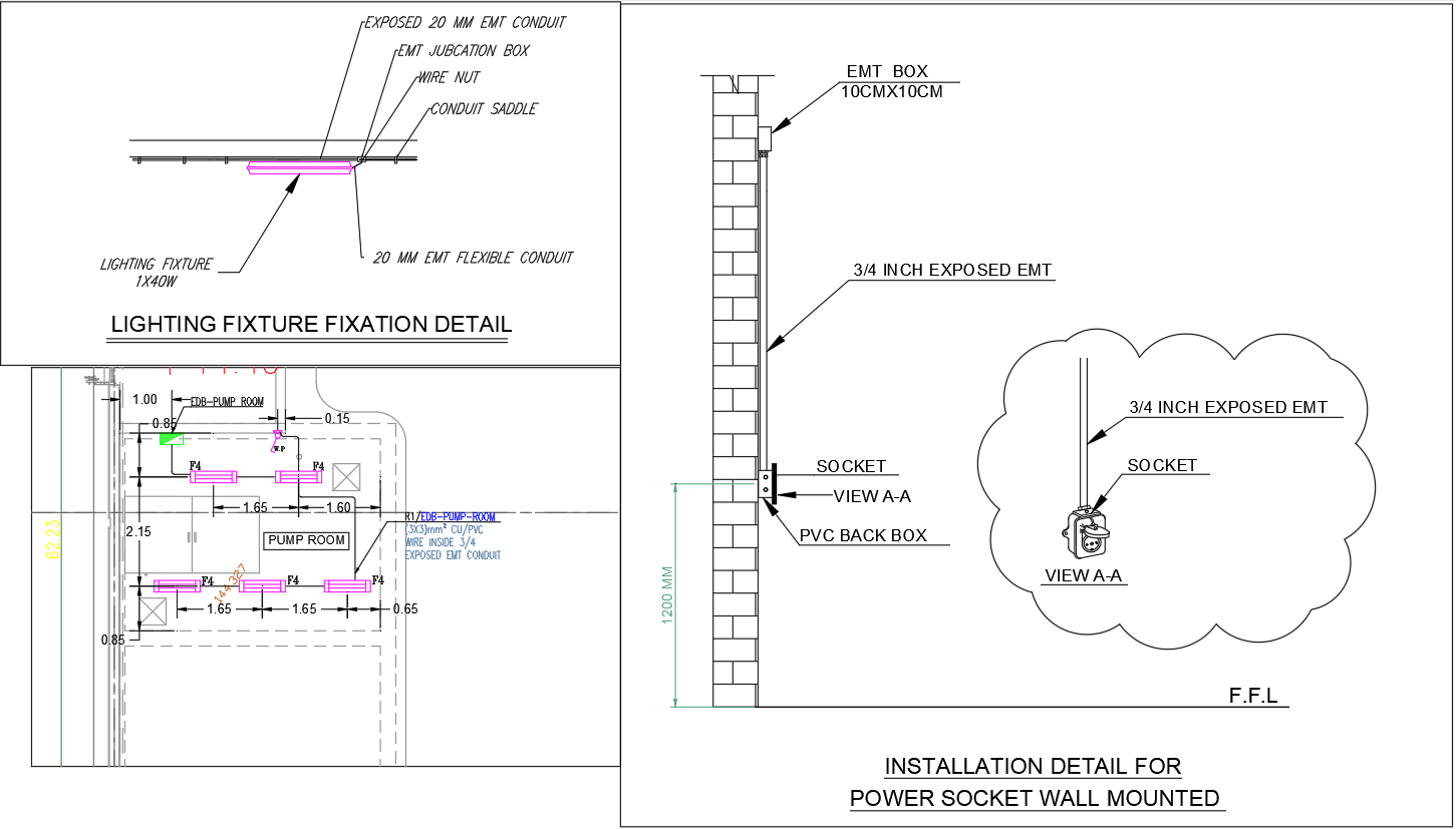
This AutoCAD DWG file presents a complete set of lighting and wall-mounted socket installation details, featuring EMT conduit routing, fixation methods and junction box positioning. The drawing includes a lighting fixture fixation detail showing a 1x40W fixture connected through a 20 mm exposed EMT conduit, 20 mm flexible conduit, conduit saddles and a properly mounted EMT junction box. Clear measurements indicate spacing between fixtures, offset dimensions and conduit alignment across the pump room ceiling layout. The lighting plan also shows the distribution of fittings marked P4, along with routing distances such as 1.65 m and 1.60 m between lamp points for uniform illumination.
The socket installation detail includes a vertical section featuring a 10 cm x 10 cm EMT box, PVC back box, and 3/4 inch exposed EMT conduit rising from floor level to a mounting height of 1200 mm. The DWG shows View A-A illustrating how the conduit interfaces with the wall surface and the socket box for safe electrical installation. These detailed drawings are ideal for electrical engineers, site supervisors and contractors needing accurate reference for conduit layout, lighting mounting and power point placement within technical rooms and service areas.

Uploaded by:
Eiz
Luna
