Rainwater Gutter and Downpipe Drainage System Detailed AutoCAD DWG
Description
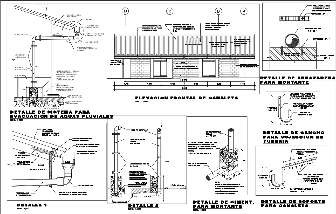
This AutoCAD DWG drawing provides a comprehensive rainwater gutter and downpipe drainage system design intended for accurate building construction and stormwater management planning. The drawing includes a clear front elevation of the gutter canaleta system, showing its alignment along the roof edge with precise fixing points and spacing. Detailed sectional views illustrate roof slope connections, gutter profiles, water flow direction, and pipe diameter references. The layout also presents downpipe routing from roof level to ground level, ensuring effective rainwater evacuation. All structural interfaces are carefully detailed to support practical installation and coordination on site.
In addition, the DWG file contains enlarged construction details for pipe clamps, mounting brackets, hooks, and support elements used to fix the drainage system securely to walls and structural members. Foundation and base details for vertical pipes are shown with dimensions, concrete specifications, and fixing methods to ensure long term durability. The drawing clearly indicates material connections, alignment tolerances, and installation clearances required for efficient drainage performance. This rainwater drainage drawing is ideal for architects, civil engineers, and construction professionals who need reliable technical documentation for residential, commercial, or industrial building projects.
File Type:
DWG
File Size:
1 MB
Category::
Construction
Sub Category::
Construction Detail Drawings
type:
Gold
Uploaded by:
K.H.J
Jani
