Welding Joint Radiography AutoCAD Sketch For Pressure Vessel

Ratings & Reviews
Be the first to share your experience with this product. Your review helps others make better decisions!
Description
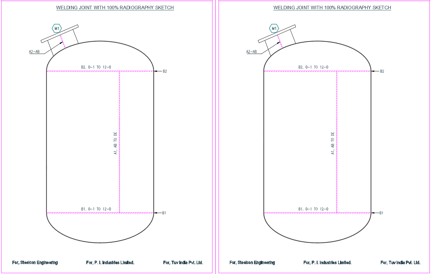
This welding joint radiography AutoCAD sketch provides a detailed technical drawing prepared for pressure vessel fabrication and inspection requirements. The sketch illustrates longitudinal and circumferential welding joints with clear identification of weld paths marked for 100 percent radiographic testing. Top and bottom shell welds are shown with proper labeling, such as B1 and B2 joints, including weld length reference from 0 1 to 12 0 for full circumference coverage. Nozzle connection welding details are also indicated with angular placement to ensure accurate fabrication alignment. The drawing layout supports quality control procedures by clearly defining weld locations subjected to radiography.
The CAD drawing is structured to meet industrial inspection standards and fabrication documentation needs. Weld joint continuity, vertical and horizontal weld alignment, and inspection zones are clearly highlighted for execution clarity. This sketch is suitable for pressure vessel manufacturing plants, fabrication engineers, and quality inspectors requiring precise AutoCAD documentation for non-destructive testing compliance. All annotations, line types, and references are presented in a clean technical format suitable for shop drawings, inspection records, and approval submissions in industrial engineering projects.
File Type:
DWG
File Size:
104 KB
Category::
Mechanical and Machinery
Sub Category::
Factory Machinery
type:
Free
Tags
Uploaded by:
akansha
ghatge
Ratings & Reviews
Be the first to share your experience with this product. Your review helps others make better decisions!