Retaining Wall Autocad Section with Reinforcement and Footing Details
Ratings & Reviews
Be the first to share your experience with this product. Your review helps others make better decisions!
Description
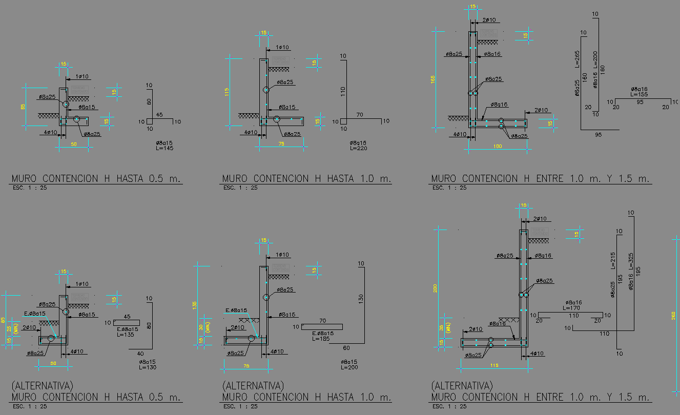
This structural AutoCAD layout provides complete retaining wall section drawings for heights ranging from 0.5 m to 2.0 m, including standard and alternative wall designs. The drawing on page 1 shows reinforced concrete (RC) walls with footing widths, heel projections, and stem thicknesses clearly dimensioned. Each wall type indicates reinforcement bar placement, including vertical rebars, horizontal ties, and base steel, along with hook lengths and minimum bending radii.
General specifications listed in the bottom section outline design bases, concrete mix requirements, rebar grades, and minimum cover conditions. The sheet also includes labeled footing depths, stem elevations, compacted backfill lines, and drainage indications where applicable. Alternative retaining wall options provide variations in heel length, toe size, and reinforcement configuration for height categories 0.5 m, 1.0 m, 1.0–1.5 m, and 1.5–2.0 m. This DWG drawing is ideal for architects, civil engineers, and structural designers working on slope protection, earth retention, and foundation stability.
File Type:
DWG
File Size:
150 KB
Category::
Structure
Sub Category::
Section Plan CAD Blocks & DWG Drawing Models
type:
Gold
Tags
Uploaded by:
Ratings & Reviews
Be the first to share your experience with this product. Your review helps others make better decisions!