Instrument cable tray routing CAD layout with elevation view
Ratings & Reviews
Be the first to share your experience with this product. Your review helps others make better decisions!
Description
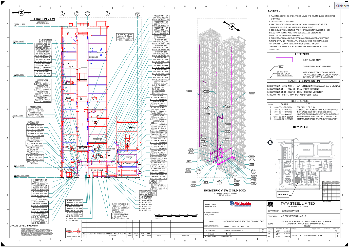
This AutoCAD DWG presents a complete instrument cable tray routing CAD layout for the Cold Box, Argon Box, and Exchanger Box areas within the Tata Steel Kalinganagar ASU facility. The elevation view, drawn at a 1:150 scale, includes detailed tray sizes such as 300 mm x 100 mm, 600 mm x 100 mm, 200 mm x 50 mm, 500 mm x 100 mm, and 400 mm x 100 mm, along with Bottom of Tray elevations ranging from EL. 59600 mm to EL. 110300 mm. Each tray line is tagged with unique IDs like K19001IWN03, K19001IWN04, K19001IWT02, and K1JDNA011006, helping users understand exact routing, vertical transitions, and connection locations. The drawing also highlights main battery limits, cable part numbers, and direction markers (Looking West / Looking Southwest) to ensure correct interpretation during installation.
The right side contains an isometric view of the Cold Box structure, showing cable trays in 3D space for better visual clarity. Legends define tray types, tray sizes, junction box routing, and naming conventions such as K19001WN01-01 and K19001WN01-01-01 for branching. A structured reference table identifies related drawings, including overall routing layouts and junction box wiring diagrams. Notes specify installation rules, such as maximum tray support spacing of 2000 mm for horizontal and 1500 mm for vertical runs, along with design responsibilities for field subcontractors. With precise coordinates, elevations, and routing lines, this DWG is ideal for architects, engineers, and industrial designers needing accurate instrument cable tray layout details.
File Type:
DWG
File Size:
1.3 MB
Category::
Electrical
Sub Category::
Electrical Automation Systems
type:
Gold
Tags
Uploaded by:
Priyanka
Patel
Ratings & Reviews
Be the first to share your experience with this product. Your review helps others make better decisions!