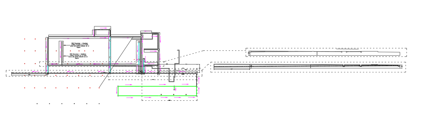
Structural Foundation Section Detail with Beam Depth Levels Plan

Ratings & Reviews
Be the first to share your experience with this product. Your review helps others make better decisions!
Description
This AutoCAD DWG file provides a highly detailed Structural Foundation Section Detail, showing the complete formation of footing levels, foundation beams, and vertical alignment across the structural section. The drawing includes precise measurements such as 88.2000, 42.0003, 26.2345, 13.4284, 10.4795, 18.1434, 7.7650, 3.9804, 16.9566, 1.9150, and 2.1465, which represent foundation depths, slab elevations, structural transitions, and connection points between walls and footing elements. A highlighted beam section in green illustrates the main load-bearing beam, while dashed outlines and directional arrows show how the structure aligns across the horizontal and vertical axes. The section also reveals stepped footing conditions and slab interfaces essential for engineering and construction accuracy. Additional elements in the drawing include reinforcement indicator lines, slope references, joint placements, and structural cut lines that define how forces transfer through the foundation. The combination of depth markers and footing widths offers clear guidance for excavation planning, reinforcement installation, and concrete pouring. This DWG is ideal for structural engineers, architects, civil contractors, and BIM professionals who require an editable and exact foundation section for construction documentation. Its clarity and accuracy support better coordination across AutoCAD, Revit, SketchUp, and 3ds Max, ensuring reliable structural detailing during project execution
Tags
Uploaded by:
john
kelly
Ratings & Reviews
Be the first to share your experience with this product. Your review helps others make better decisions!