Pressure Vessel Layout with Nozzle Flange Pipe and Elevation Data

Ratings & Reviews
Be the first to share your experience with this product. Your review helps others make better decisions!
Description
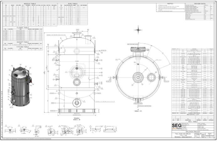
This pressure vessel general arrangement drawing provides complete dimensional details required for accurate fabrication and installation. The plan includes a clear top view, side elevation, and sectional representation, showing precise measurements for the vessel diameter, total height, and shell length. All nozzle positions are marked with centerline dimensions, flange sizes, gasket types, and bolt arrangements, ensuring proper alignment during assembly. The drawing also highlights the manhole, support pads, and weld joint locations, helping engineers understand the structural configuration.
Additionally, the file contains a detailed nozzle schedule, fitting table, and flange table that specify material grades, thickness values, and connection types. Each component, including valves, reducers, tees, and couplings identified for easy procurement and workshop reference. Elevation markings and descriptive labels help professionals verify the correct installation height and orientation. This layout is ideal for architects, civil engineers, mechanical designers, and fabrication teams who require accurate construction drawings for industrial equipment. The measurements and technical details included in this AutoCAD drawing support precise planning, modeling, and on-site execution.
File Type:
DWG
File Size:
423 KB
Category::
Mechanical and Machinery
Sub Category::
Factory Machinery
type:
Gold
Tags
Uploaded by:
Jafania
Waxy
Ratings & Reviews
Be the first to share your experience with this product. Your review helps others make better decisions!