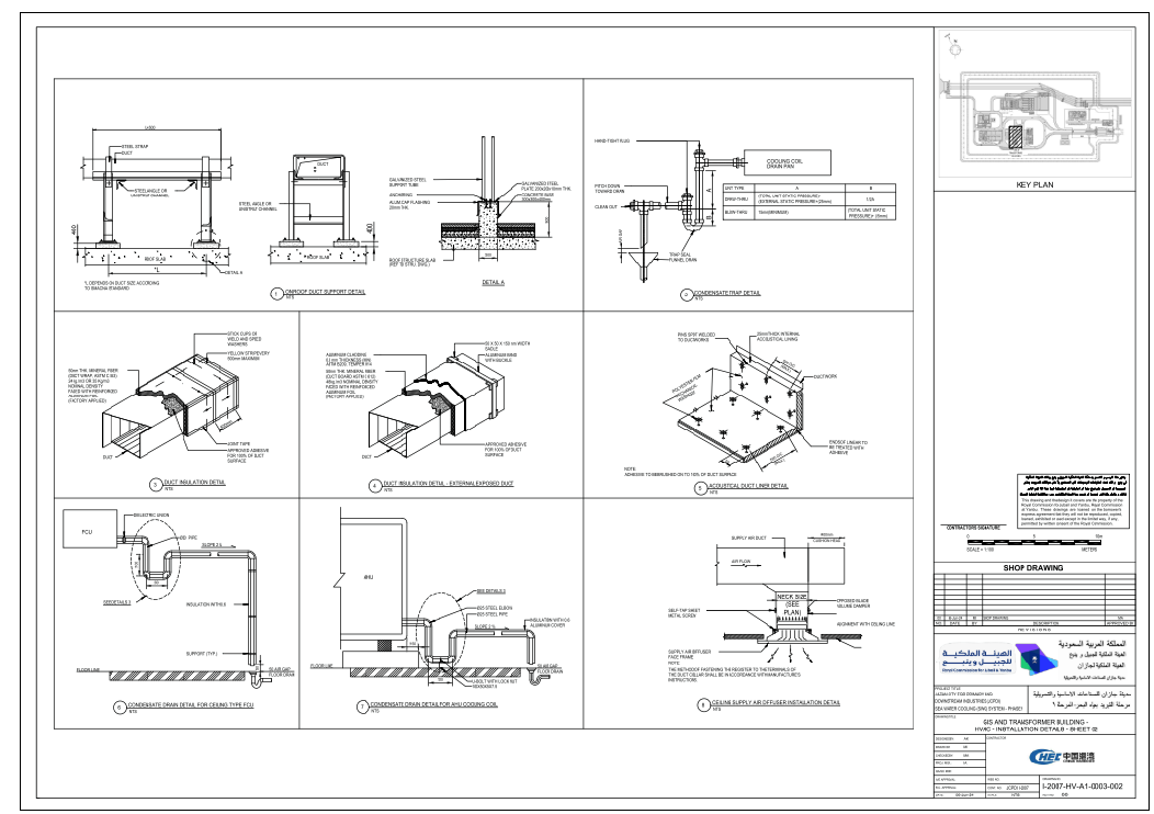
HVAC Installation Details with Duct and Drainage Plan 6.00 Layout

Ratings & Reviews
Be the first to share your experience with this product. Your review helps others make better decisions!
Description
This HVAC installation detail drawing provides a complete technical layout of duct supports, condensate traps, acoustic duct lining, insulation methods, aluminum cladding applications, and drainage connections for both AHU and FCU systems. The sheet includes precise measurements for duct elevations, pipe diameters, insulation thicknesses, galvanized support plates, U-bolt arrangements, slope percentages, and anchor points, ensuring accurate on-site implementation. Each detail shows clearly labeled dimensions such as 300×300×400 mm concrete bases, 200×200×10 mm galvanized plates, 50 mm mineral fiber insulation, 25 mm acoustic lining, coil drain pan levels, 2% slope requirements, diffuser neck sizes, and fastening techniques that follow standard HVAC construction guidelines. The drawings also feature ceiling-mounted diffuser installation details with alignment lines, reinforced foil backing notes, steel angles, unistrut supports, and duct wrap applications.
This AutoCAD-based layout is ideal for architects, civil engineers, builders, and MEP designers who require accurate ducting, drainage, and equipment connection references for professional HVAC projects. The detailed sectional views make it easier to coordinate mechanical layouts with structural and architectural components, ensuring efficient installation and long-lasting system performance.
Tags
Uploaded by:
Wang
Fang
Ratings & Reviews
Be the first to share your experience with this product. Your review helps others make better decisions!