40FT Air Assisted Flare System DWG with Nozzle and Pilot Layout
Ratings & Reviews
Be the first to share your experience with this product. Your review helps others make better decisions!
Description
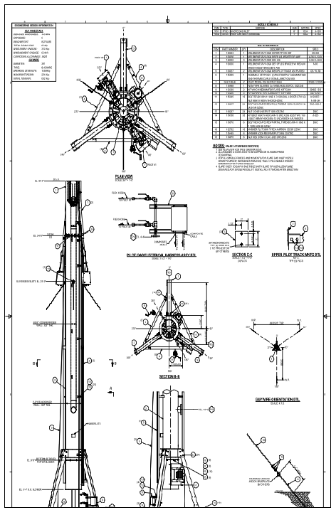
This AutoCAD DWG file features a complete 40FT air-assisted flare system layout, including structural, mechanical, and installation details as shown in the elevation, plan view, and sectional diagrams on page 1. The elevation drawing clearly marks critical heights such as EL. 40'-0" overall height, EL. 34'-0" nozzle elevation, EL. 29'-0" guywire eyelets, EL. 15'-0" riser transition, EL. 9'-6" nameplate, and EL. 6'-4" blower bottom. Plan view includes the full circular orientation of the flare legs, pilot assemblies, and riser positions at 0°, 60°, 120°, 180°, 240°, and 300°. The drawing also specifies the 8-inch waste gas inlet (TP01) and 1-inch pilot gas inlet (TP02), along with composite cable routes, flex hose connections, and anchor bolt locations.
Section B-B and Section C-C illustrate internal riser construction, showing the 2'-0" OD air riser with .322-inch wall thickness and the 8?-inch OD inner riser. The Bill of Materials lists pilot tracks, blower assembly, guywire kits, weldments, and structural supports made from 316 SS, A36, A53-B, and galvanized steel. Guywire orientation and anchor details provide installation clarity for industrial settings. This DWG is ideal for engineers, designers, and contractors working with air-assisted flare system layouts, complemented by building services coordination references such as vertical plumbing riser layout drawings prepared for twin towers in AutoCAD DWG format for integrated system planning.
File Type:
DWG
File Size:
526 KB
Category::
Dwg Cad Blocks
Sub Category::
Cad Logo And Symbol Block
type:
Gold
Tags
Uploaded by:
Priyanka
Patel
Ratings & Reviews
Be the first to share your experience with this product. Your review helps others make better decisions!