Typical Elevator Pit Plan and Section Drawing for Building Projects

Ratings & Reviews
Be the first to share your experience with this product. Your review helps others make better decisions!
Description
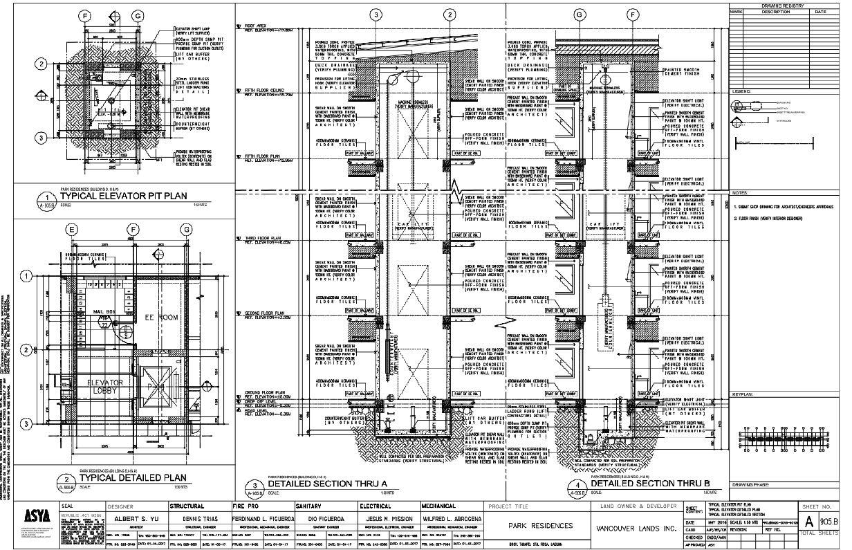
This drawing presents a typical elevator pit plan prepared for accurate construction coordination and vertical circulation planning. The layout explains pit depth, shaft alignment, wall thickness, and level relationships required during lift installation. Clear dimensioning and grid references support coordination between architectural intent and construction execution. The drawing helps professionals understand how elevator pits integrate within building layouts and service zones. Foundation level clarity is further supported by Construction Details. This reference helps ensure correct execution and coordination during early construction stages without affecting overall layout understanding.
The drawing set also includes detailed vertical sections that illustrate floor-to-floor relationships, slab levels, and shaft continuity across multiple levels. These sections support execution clarity and construction sequencing during different project stages. Material and structural understanding is enhanced through Reinforced Cement Concrete Details. Circulation coordination within the building layout is supported separately by Staircase Details, helping align vertical movement elements with the overall planning and coordination process.
File Type:
DWG
File Size:
1.8 MB
Category::
Mechanical and Machinery
Sub Category::
Elevator Details
type:
Gold
Tags
Uploaded by:
Jafania
Waxy
Ratings & Reviews
Be the first to share your experience with this product. Your review helps others make better decisions!