Aluminium Louver Door Screen Typical Construction Detail Drawing

Ratings & Reviews
Be the first to share your experience with this product. Your review helps others make better decisions!
Description
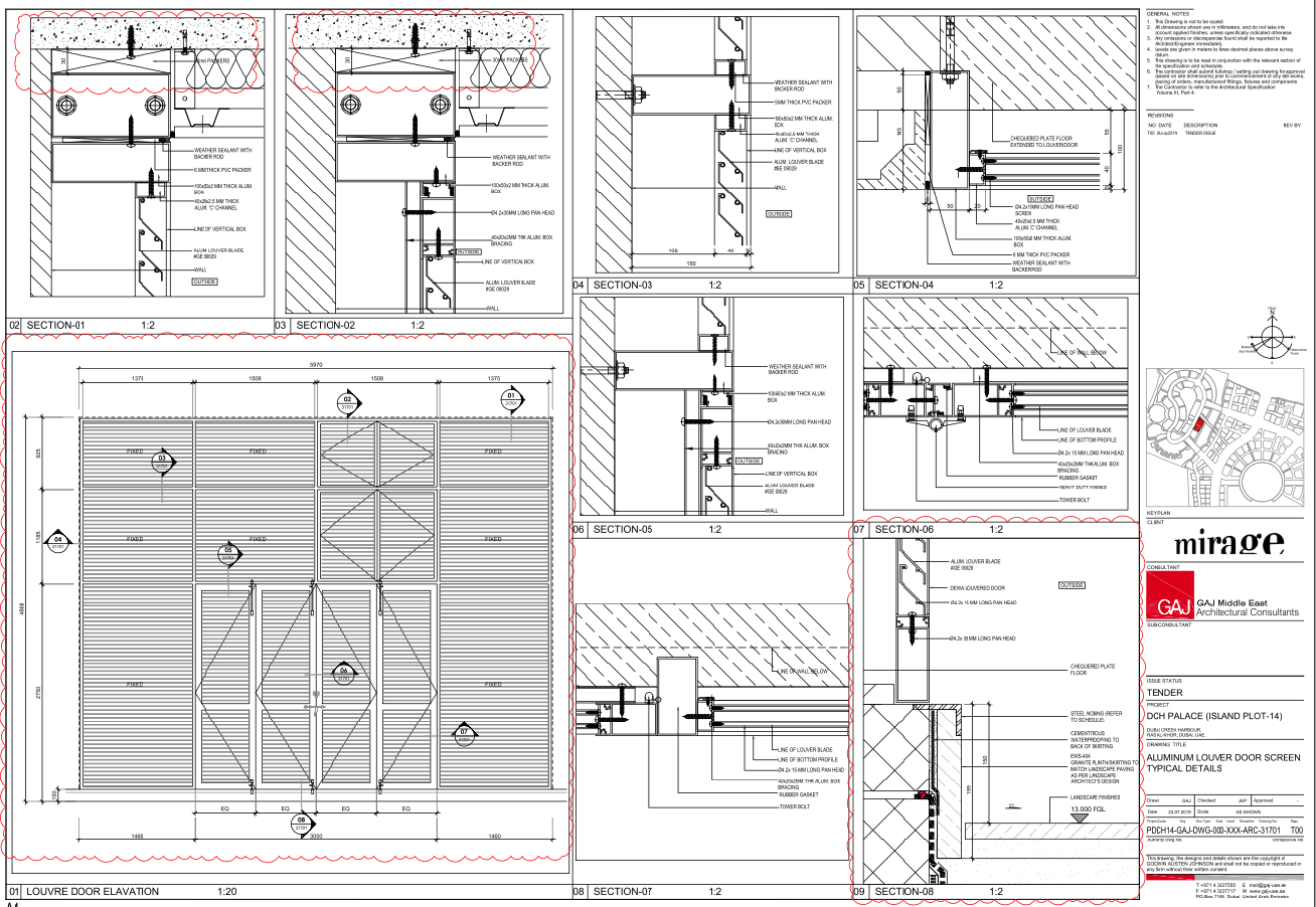
This AutoCAD drawing presents detailed typical construction information for an aluminium louvre door screen system used in architectural façade and opening treatments. The drawing includes a louvre door elevation, fixing layout, and multiple sectional details showing connection with the wall, floor, and structural edges. Material specifications such as aluminium box sections, louvre blades, PVC packers, weather sealant, and fastener locations are clearly illustrated for accurate site execution. Construction clarity is achieved through Construction Detail Drawings, which help in understanding installation sequencing, alignment control, and fixing methodology for aluminium louvre assemblies.
The drawing also focuses on close-up detailing required for fabrication and on-site coordination. Junctions with chequered plate flooring, wall interfaces, and waterproofing zones are clearly represented to avoid execution conflicts. Material junctions and interface conditions are explained using Architectural Detail Drawings, supporting accurate interpretation of edge conditions and finishes. Door operation elements and fixing supports are further detailed through Interior Details, helping designers and contractors understand functional integration within architectural openings. These drawings are suitable for architects, façade consultants, and construction professionals who require precise and editable AutoCAD files for aluminium louvre door screen detailing and installation planning, supplemented by interior layout drafting resources such as living apartment project and kitchen area layout plan CAD drawings prepared in AutoCAD DWG format for spatial coordination reference.
Tags
Uploaded by:
Harriet
Burrows
Ratings & Reviews
Be the first to share your experience with this product. Your review helps others make better decisions!