Exhaust Fan Schedule with Installation Details AutoCAD DWG File

Ratings & Reviews
Be the first to share your experience with this product. Your review helps others make better decisions!
Description
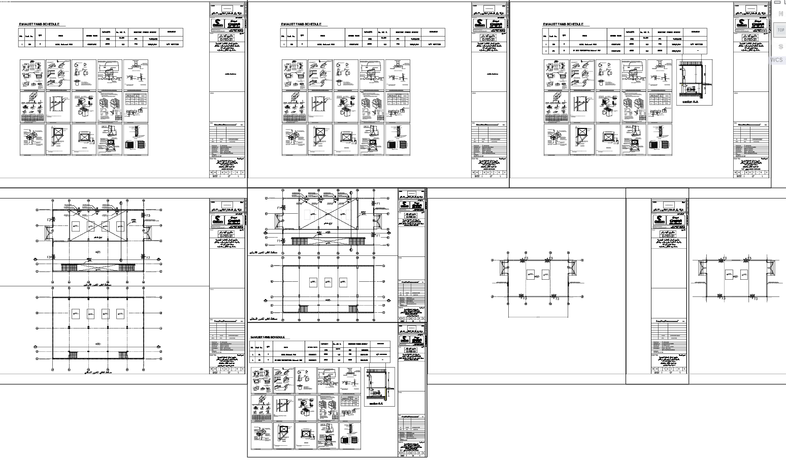
This AutoCAD drawing set presents a complete exhaust fan schedule and detailed installation layouts designed for building ventilation planning. The drawing clearly specifies axial exhaust fan units with a capacity of 2600 CFM, operating at 0.3 in WG external static pressure, and powered by a 220V single-phase 50 Hz electrical supply. The schedule table includes unit numbers, quantity, fan type, speed type, air volume, static pressure, power rating, and remarks, ensuring accurate equipment selection for mechanical and HVAC coordination. Dimensioned plans show precise fan positioning, shaft layouts, wall penetrations, and mounting references required for execution on site.
The file also includes multiple enlarged construction and installation details, such as exhaust fan fixing methods, wall sleeve arrangements, shutter connections, louver details, vibration isolation, and sectional views. These drawings help architects, civil engineers, and MEP consultants understand coordination between structure and services. The layouts are drafted to scale with clear annotations, making them suitable for tender drawings, approval submissions, and construction documentation. This AutoCAD DWG file is ideal for professionals working on residential, commercial, or utility buildings who require reliable exhaust ventilation drawings with measurable dimensions and standardized symbols for efficient project delivery with reference to mechanical component detailed CAD drawings that demonstrate similar standards of equipment detailing, installation clarity, service coordination, and construction-ready MEP documentation.
File Type:
DWG
File Size:
17.6 MB
Category::
Mechanical and Machinery
Sub Category::
Mechanical Engineering
type:
Gold
Tags
Uploaded by:
john
kelly
Ratings & Reviews
Be the first to share your experience with this product. Your review helps others make better decisions!