RCC Box Culvert Reinforcement Wing Wall And Section Detail Drawing

Ratings & Reviews
Be the first to share your experience with this product. Your review helps others make better decisions!
Description
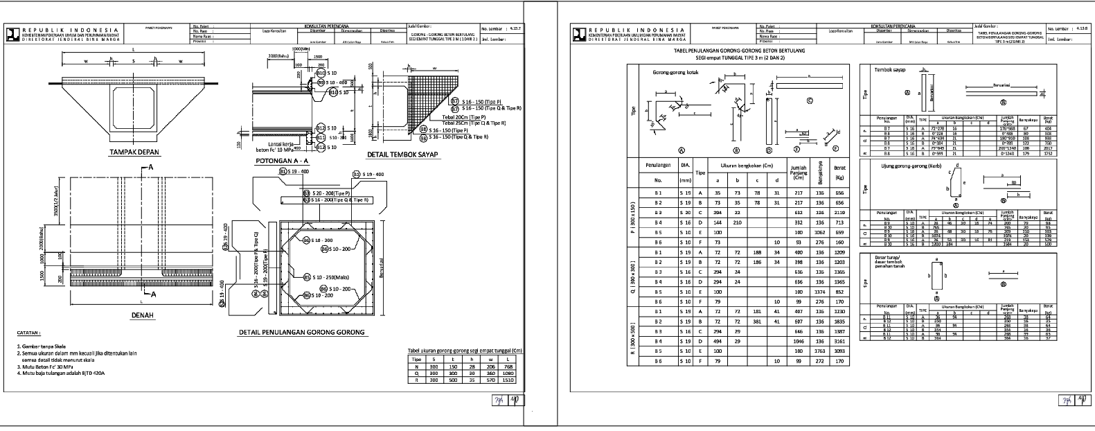
This AutoCAD drawing provides detailed structural information for an RCC box culvert, including reinforcement layout, wing wall detailing, and sectional views. The drawings show front elevation, plan, and section A–A with clear dimensions for slab thickness, wall height, base width, and culvert opening size. Reinforcement detailing includes bar diameters, spacing, bending shapes, and placement for slabs, walls, and bases. Separate tables define bar bending schedules, quantities, lengths, and weight calculations to support accurate estimation and fabrication. This drawing set is suitable for infrastructure projects linked with Road & Bridge works and Structure Drawing documentation, where precise culvert construction details are required for execution and approval.
The culvert detail drawings also include wing wall reinforcement, kerb detailing, and concrete grade notes for construction clarity. Sectional drawings explain load transfer, slab support conditions, and reinforcement continuity across structural elements. These drawings assist civil engineers and site teams during formwork preparation, reinforcement fixing, and concreting stages. The AutoCAD DWG file supports coordination with Construction Details and Architectural Detail Drawings to maintain consistency between structural design and site execution. This drawing set is suitable for use in road drainage systems, underpass structures, and small bridge projects requiring standardized RCC box culvert detailing.
File Type:
DWG
File Size:
6.8 MB
Category::
Construction
Sub Category::
Reinforced Cement Concrete Details
type:
Gold
Tags
Uploaded by:
john
kelly
Ratings & Reviews
Be the first to share your experience with this product. Your review helps others make better decisions!