Box Girder Bridge Section Drawing With Node Details And Dimensions

Ratings & Reviews
Be the first to share your experience with this product. Your review helps others make better decisions!
Description
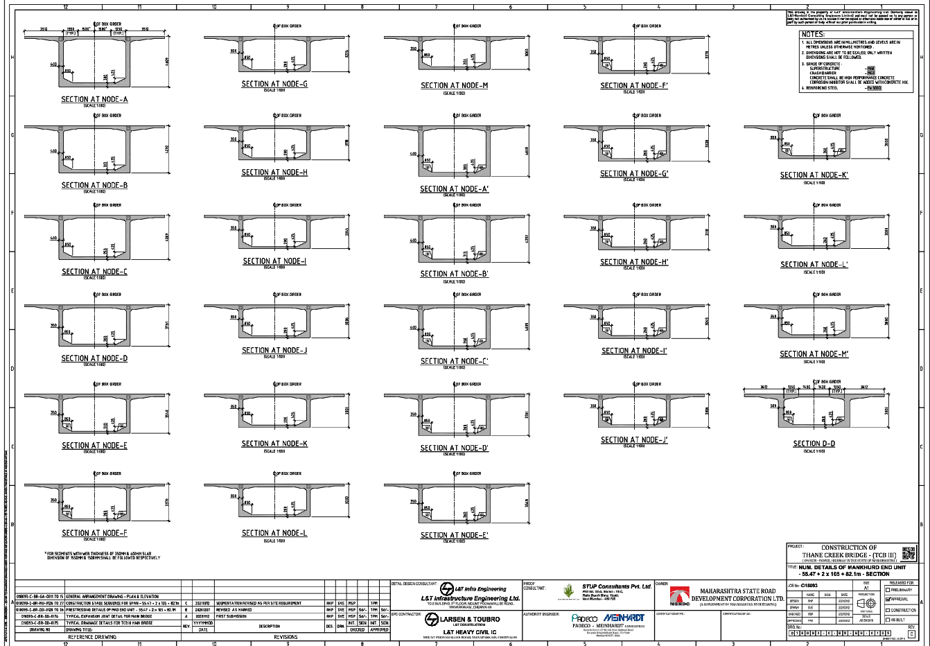
This AutoCAD DWG drawing presents detailed box girder bridge section drawings, including multiple node sections labeled from Node A to Node M. The drawing clearly shows reinforced concrete box girder cross sections with precise dimensions, slab thickness, web thickness, soffit profile, and bearing levels.
Each section illustrates variations in geometry across different nodes of the bridge span, supporting accurate structural coordination. The drawing also includes notes, scale references, and construction guidelines suitable for highway and infrastructure projects. This box girder section drawing is ideal for engineers and designers requiring clear dimensional data and standardized bridge detailing in AutoCAD format.
Tags
Uploaded by:
john
kelly
Ratings & Reviews
Be the first to share your experience with this product. Your review helps others make better decisions!