Mechanical Roof Floor Plan Drawing With HVAC Duct Dimensions

Ratings & Reviews
Be the first to share your experience with this product. Your review helps others make better decisions!
Description
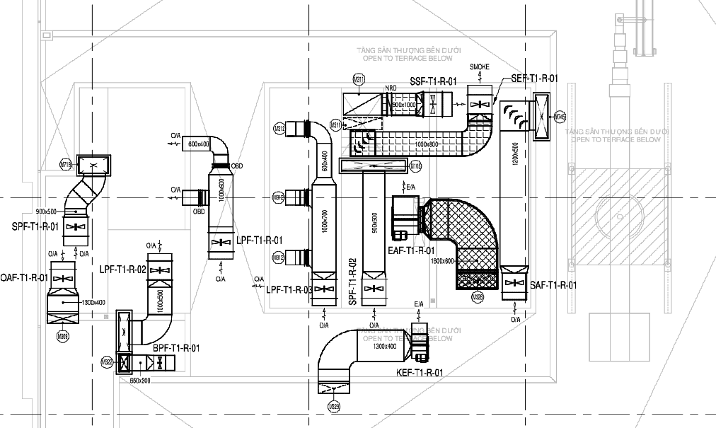
This AutoCAD DWG file illustrates a mechanical roof floor plan drawing developed for a high-rise commercial building with integrated HVAC and ventilation systems. The plan represents Tower 1 roof level layout, clearly showing duct routing, riser positions, and equipment zoning across the terrace area. Mechanical components such as outside air ducts, smoke exhaust ducts, pressure air ducts, kitchen exhaust ducts, and buffer room pressurization ducts are precisely marked. Duct sizes including 2600 x 400 mm, 1250 x 650 mm, 1800 x 500 mm, 1600 x 600 mm, 1300 x 400 mm, and 900 x 500 mm are clearly indicated, supporting accurate coordination and clash-free execution. Grid lines, structural references, and open-to-terrace below zones help define spatial alignment at the roof level.
The drawing further identifies pressurization risers for staircases and refuge areas, smoke exhaust paths, fresh air intake routes, and exhaust discharge points. Each mechanical element is coded and referenced for coordination with MEP and fire safety drawings. Dimensions are presented in millimeters, ensuring consistency with construction standards and technical documentation. Notes, legends, and key plans assist professionals in understanding airflow direction, system purpose, and equipment placement. This DWG file is suitable for architects, civil engineers, interior designers, builders, and MEP professionals using AutoCAD, Revit, 3D Max, and SketchUp for mechanical planning, HVAC coordination, and professional roof level service design, and is directly related to detailed commercial HVAC layout CAD drawings that focus on roof-level duct routing, riser coordination, and execution-ready mechanical service planning.
Tags
Uploaded by:
Niraj
yadav
Ratings & Reviews
Be the first to share your experience with this product. Your review helps others make better decisions!