Electrical Control Panel Wiring Diagram With Auto Manual Control
Tags
Ratings & Reviews
Be the first to share your experience with this product. Your review helps others make better decisions!
Description
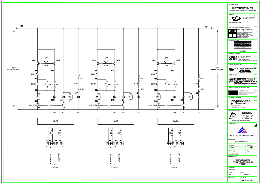
This AutoCAD DWG file presents a detailed electrical control panel wiring diagram prepared for power zone and equipment control applications. The drawing illustrates complete control logic with a 220V supply, clearly marked start stop circuits, trip conditions, and auto manual selector switches. Components such as contactors KM4, KM5, and KM6, overload relays OL4, OL5, and OL6, auxiliary relays, indicator lamps, and terminal numbering are precisely shown for execution accuracy. Control elements like STOP and START push buttons, auto manual switches SS4, SS5, and SS6, and status indicators for ON, OFF, and TRIP conditions are logically arranged. Reference numbering, coil connections, and interlocking paths ensure a correct understanding of operational sequencing and fault protection.
The wiring schematic also defines alarm and status feedback using indicators LA 66, LA 67, and LA 74, supporting monitoring during operation. Circuit continuity, control voltage paths, and protection logic are clearly represented to assist panel fabrication, testing, and maintenance. All symbols follow standard electrical drafting conventions, making the drawing suitable for coordination with mechanical and MEP systems. This DWG file supports architects, civil engineers, electrical consultants, interior designers, builders, and BIM professionals working with AutoCAD, Revit, 3D Max, and SketchUp. It serves as a reliable reference for electrical control panel design, automation coordination, and professional construction documentation in commercial and hospitality projects.

Uploaded by:
john kelly
Tags
Ratings & Reviews
Be the first to share your experience with this product. Your review helps others make better decisions!