Proposed Residential Building Plan With Site Layout Elevations

Ratings & Reviews
Be the first to share your experience with this product. Your review helps others make better decisions!
Description
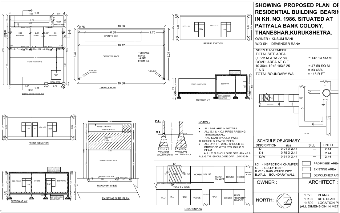
This AutoCAD DWG drawing illustrates a proposed residential building plan prepared with complete architectural and site-level details. The drawing includes an existing ground floor plan showing room layouts with clear internal dimensions, front courtyard planning, bedroom and store arrangement, toilet positioning, and main entry access. A terrace plan is provided with an overall size of 10.36 m by 6.37 m, highlighting open to sky zones, terrace level noted at plus 4.04 m from ground level, and parapet wall alignment. Front and rear elevations display door and window placements with level markings such as plus 0.00 and minus 2.13, supporting height coordination. Sections at X X and Y Y explain foundation depth, wall thickness, and slab positioning for structural clarity.
The drawing also contains a detailed area statement with a total site area of 142.13 square metres based on plot dimensions of 10.36 m by 13.72 m. Covered area at the ground floor is calculated as 47.59 square metres with an F A R of 33.46 percent. The boundary wall length is marked as 116 running feet. Site plan and location plan indicate road width of 6 m, plot orientation, and surrounding context. Construction notes specify that all dimensions are in metres, sleeve pipes are required for services passing through walls and slabs, 115 mm walls must be supported with 230 x 230 mm RCC beams, inspection chambers sized 0.46 x 0.46 m, and gully traps sized 0.30 x 0.30 m. This residential plan drawing supports architectural approval, planning coordination, and execution accuracy.
Tags
Uploaded by:
Jafania
Waxy
Ratings & Reviews
Be the first to share your experience with this product. Your review helps others make better decisions!