Mezzanine Level AHU PAU Room Layout with Duct Sizes and Sections

Ratings & Reviews
Be the first to share your experience with this product. Your review helps others make better decisions!
Description
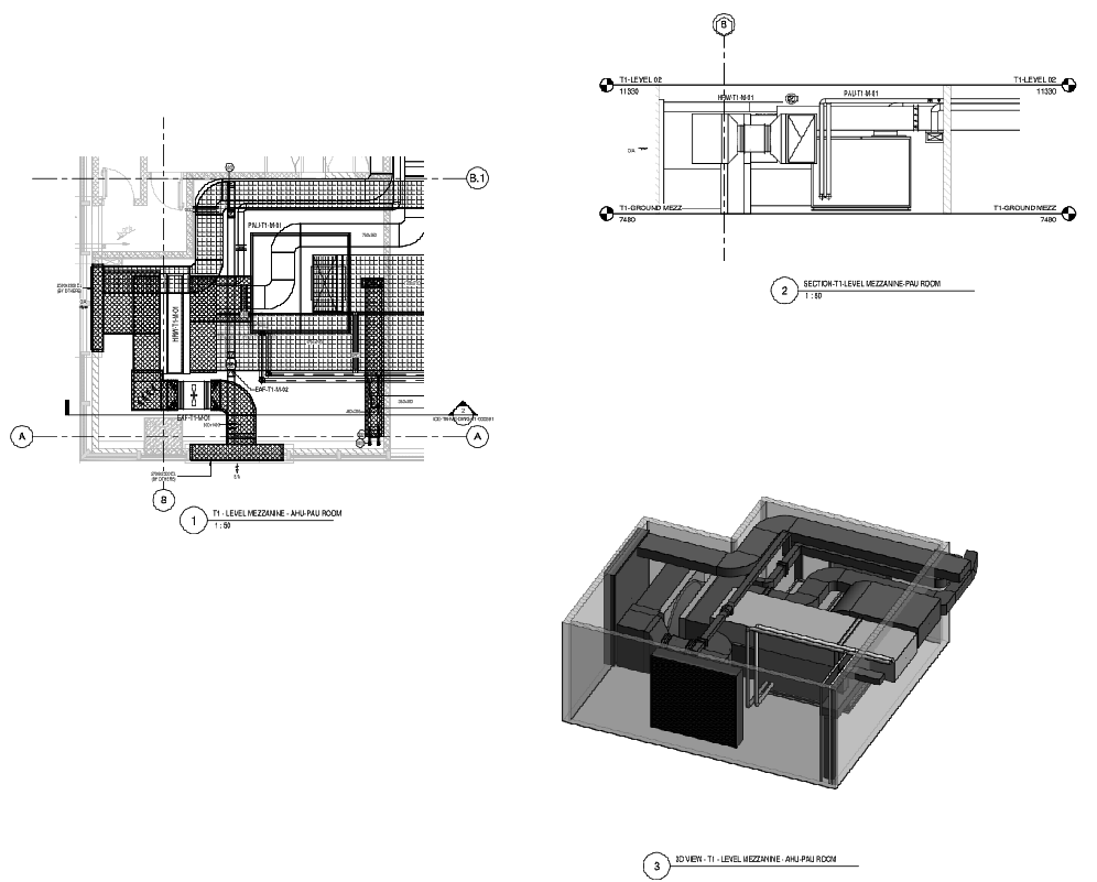
This AutoCAD DWG drawing illustrates a detailed mezzanine-level AHU and PAU room layout with coordinated mechanical services planning. The plan shows an AHU and PAU room area of approximately 60.29 square meters, clearly marked with equipment locations, airflow paths, and duct routing. Major components such as PAU T1 M 01, exhaust air fans, heat recovery wheel units, and outside air connections are positioned with precise clearances. Duct sizes including 1700 x 700 mm, 800 x 1400 mm, 700 x 350 mm, 450 x 200 mm, and 350 x 200 mm are labeled to support accurate fabrication and installation. A floor slope of 2 percent is indicated for drainage coordination within the plant room.
The drawing also includes sectional views showing vertical coordination between T1 ground mezzanine level at 7480 mm and T1 level 02 at 11330 mm. Equipment elevations such as 2500 x 3500 mm and 2700 x 2500 mm are identified for integration with architectural and structural levels. A three-dimensional view is provided to clarify spatial arrangement, service access, and maintenance zones around AHU and PAU units. This drawing is suitable for mechanical engineers, MEP coordinators, and project teams who require clear plant room dimensions, duct sizing, level heights, and section references for mezzanine-level HVAC execution.
Tags
Uploaded by:
john
kelly
Ratings & Reviews
Be the first to share your experience with this product. Your review helps others make better decisions!