Plinth Beam Reinforcement Drawing with Longitudinal Sections
Tags
Ratings & Reviews
Be the first to share your experience with this product. Your review helps others make better decisions!
Description
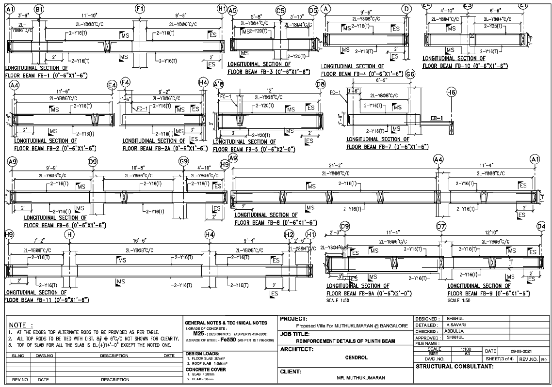
This AutoCAD DWG file contains a comprehensive plinth beam reinforcement drawing prepared for residential villa construction. The drawing illustrates multiple longitudinal sections of plinth and floor beams labelled FB 1 to FB 11 with clear span lengths ranging from approximately 3 feet 9 inches up to 24 feet 2 inches. Beam sizes are detailed around 0 feet 6 inches by 1 feet 6 inches and 0 feet 6 inches by 2 feet 0 inches, with reinforcement specifications including 2-legged 8 mm stirrups at centre-to-centre spacing, top and bottom main bars, and mid-span and end-span detailing. Material grades are specified as M25 concrete and Fe550 steel, with concrete cover noted as 30 mm for beams. The drawing also includes section references, bar marking notations, a scale of 1 is to 100, and technical notes for execution accuracy. This plinth beam reinforcement drawing is suitable for architects, civil engineers, and structural designers working on residential RCC detailing using AutoCAD DWG files, supported by urban planning reference drawings such as urban road network plans with cross-sections prepared in AutoCAD DWG format for coordinated infrastructure planning.

Uploaded by:
Harriet Burrows
Tags
Ratings & Reviews
Be the first to share your experience with this product. Your review helps others make better decisions!