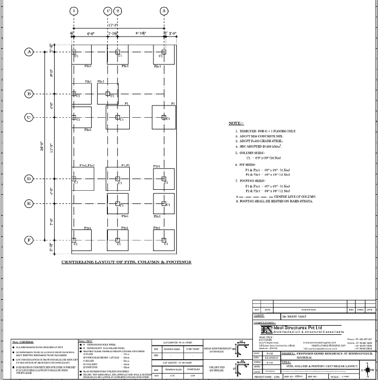
Centerline Layout of Pits, Columns and Footings with Measurements

Ratings & Reviews
Be the first to share your experience with this product. Your review helps others make better decisions!
Description
Download a professionally drafted centerline layout of pits, columns, and footings in AutoCAD DWG format for accurate structural planning. This drawing presents a detailed foundation layout with an overall building length of approximately 38 ft and a width of about 17 ft 8 in. The plan includes grid lines marked from A to F and 1 to 3, ensuring precise alignment of structural elements. Column positions are clearly labeled as C1, while pit and footing types such as P2x1, P3x1, and F1 are systematically arranged. The layout shows bay spacing of 6 ft, 7 ft 10 in, and 8 ft 10 in with 2 ft offset margins for balanced load distribution. Each footing and pit is dimensioned with centerline references for accurate site execution. This AutoCAD DWG file is ideal for architects, civil engineers, structural consultants, and builders who require ready-to-use foundation layout drawings for residential and commercial projects.
Tags
Uploaded by:
Harriet
Burrows
Ratings & Reviews
Be the first to share your experience with this product. Your review helps others make better decisions!