Chiller Plant Room HVAC Layout AutoCAD DWG with Duct Sizes files
Ratings & Reviews
Be the first to share your experience with this product. Your review helps others make better decisions!
Description
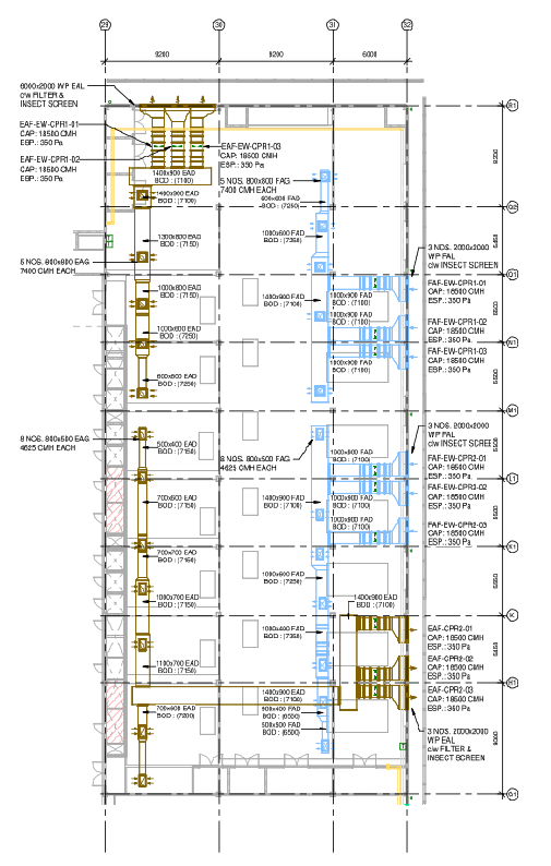
This AutoCAD DWG file presents a detailed air conditioning and mechanical ventilation layout for a chiller plant room prepared for a data centre and large-scale building services design. The drawing clearly shows the full HVAC duct routing plan with exhaust air ducts EAD and fresh air ducts FAD, including exact duct sizes such as 1400x900 mm, 1000x900 mm, 700x600 mm, 600x600 mm, and 500x400 mm. Each duct is labelled with the bottom of duct levels ranging between 6500 mm and 7350 mm, ensuring accurate vertical coordination. Equipment tags, airflow capacities like 7400 CMH and 4625 CMH, and external static pressure values of 350 Pa are clearly indicated for engineering reference. The layout also includes wall-mounted exhaust fans, fresh air fans, weatherproof louvers with insect screens, filter sections, and access spacing between duct lines. Multiple fan units with capacities of 18500 CMH are positioned with proper clearances and service access zones. All dimensions are drafted in millimeters at a 1:150 scale, making the drawing suitable for construction and coordination
File Type:
DWG
File Size:
1012 KB
Category::
Mechanical and Machinery
Sub Category::
Mechanical Engineering
type:
Gold
Tags
Uploaded by:
K.H.J
Jani
Ratings & Reviews
Be the first to share your experience with this product. Your review helps others make better decisions!