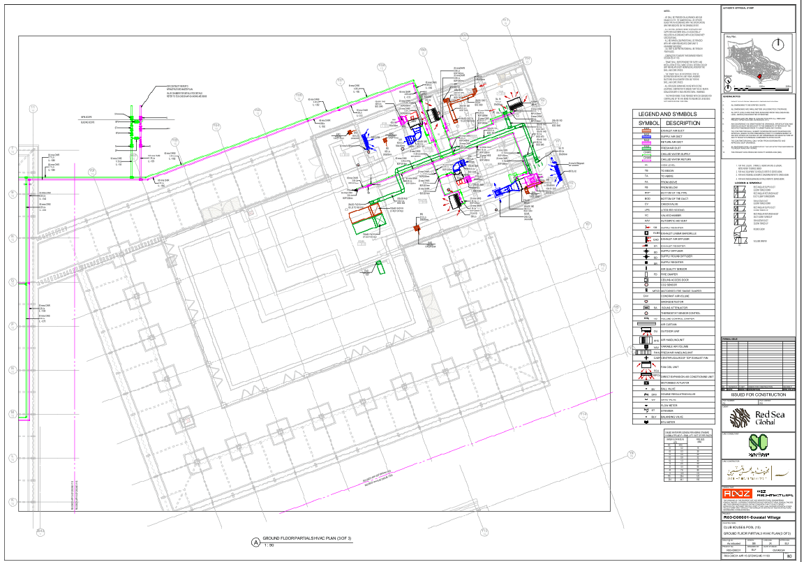
Ground Floor Partials HVAC Layout With Ducting And Pipe Details

Ratings & Reviews
Be the first to share your experience with this product. Your review helps others make better decisions!
Description
This AutoCAD DWG file provides a detailed HVAC layout for the ground floor, ensuring seamless coordination in large-scale construction projects. It features a chilled water supply and return piping system (CHWS and CHWR) with pipe diameters ranging from 20 mm to 150 mm for balanced water flow. Flow rates, from 0.29 LPS to 11.79 LPS, are carefully calculated for optimal performance. Key HVAC components, such as Fan Coil Units (FCUs), DX Fan Coil Units (DXFCUs), Fresh Air Handling Units (FAHUs), and exhaust fans, are connected through air ducts in various sizes, maximizing airflow, thermal comfort, and energy efficiency, fitting within the overall mechanical and machinery design of the project.
The layout prioritizes a smooth, clash-free installation with clearly defined locations for dampers, valves, and other components. Integrated fire and smoke dampers, air quality sensors, thermostats, and motorized actuators adhere to ASHRAE standards for optimal system performance. The HVAC system operates efficiently, maintaining comfort and meeting building code requirements and sustainability goals within the broader construction and urban design.
File Type:
DWG
File Size:
1.2 MB
Category::
Electrical
Sub Category::
Architecture Electrical Plans
type:
Gold
Tags
Uploaded by:
Niraj
yadav
Ratings & Reviews
Be the first to share your experience with this product. Your review helps others make better decisions!