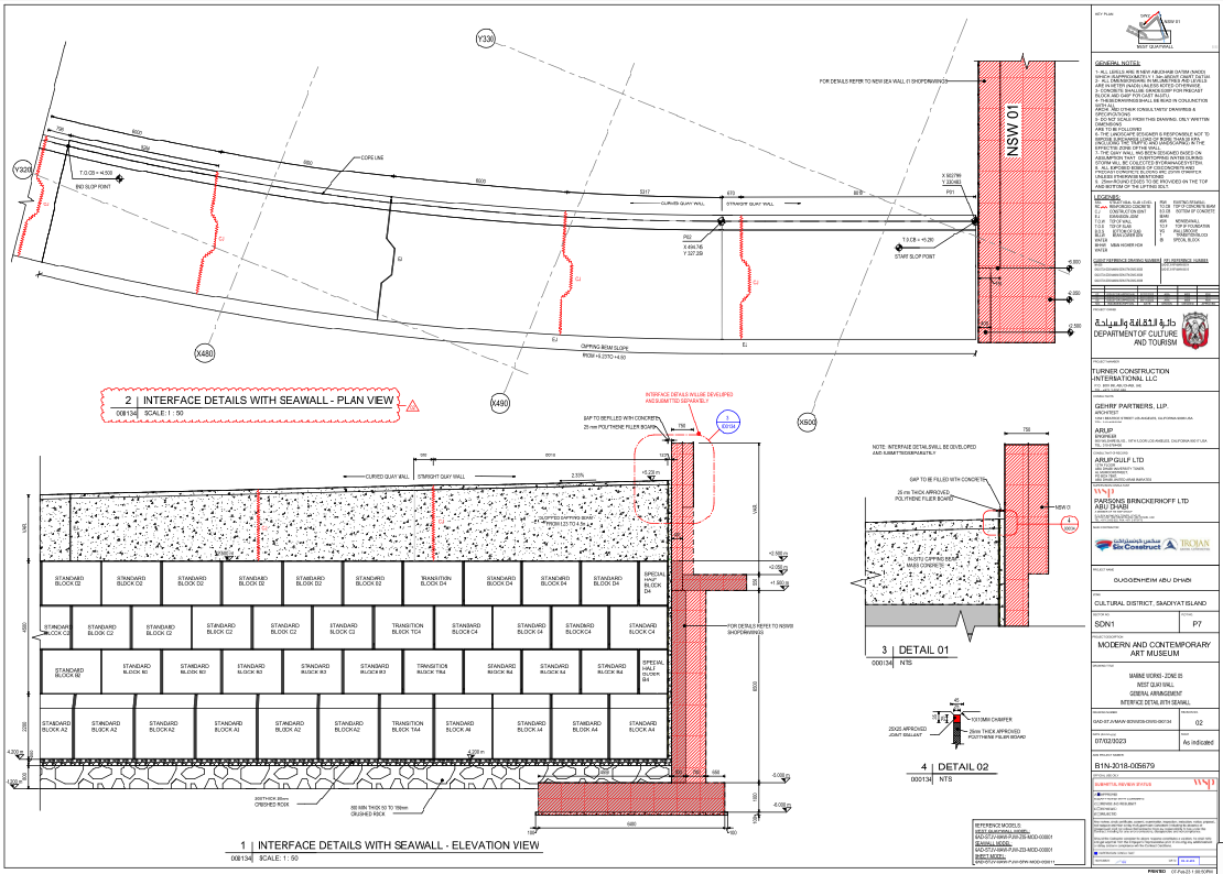
Seawall Interface Detail 8010mm Quay Wall Plan Drawing AutoCAD

Ratings & Reviews
Be the first to share your experience with this product. Your review helps others make better decisions!
Description
This AutoCAD drawing presents the Seawall Interface Detail for West Quay Wall NSW 01, showing 8010 mm straight quay wall length with 670 mm curved transition and overall 6000 mm segments. The elevation view illustrates standard block A2 B2 C2 D2 stacking overa crushed rock foundation 800 mm minimum thickness, 50 to 150 mm grading, and a 200 mm thick 20 mm crushed rock layer. Levels are defined from minus 6.000 m to plus 6.000 m with a T O C B sloped capping beam from plus 5.230 m to plus 4.500 m at a 2.33 percent gradient. The interface includes a 25 mm thick polythene filler board gap filled with concrete and a 10 by 10 mm chamfer at exposed edges. This Seawall Interface Detail AutoCAD drawing also includes a plan view with coordinates P01 at X 502.799 Y 330.483 and P02 at X 494.745 Y 327.259, referencing grid lines X480 to X500 and Y320 to Y330.
Tags
Uploaded by:
Niraj
yadav
Ratings & Reviews
Be the first to share your experience with this product. Your review helps others make better decisions!