Building Center Line Layout Plan With 84 Feet Grid Dimension DWG

Ratings & Reviews
Be the first to share your experience with this product. Your review helps others make better decisions!
Description
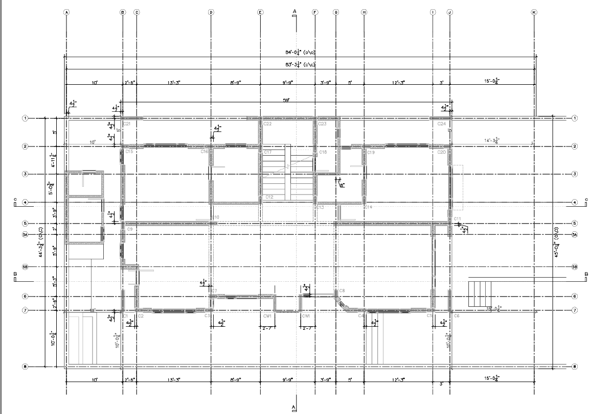
Building centre line layout plan presenting a detailed architectural grid and structural alignment drawing with an overall horizontal dimension of approximately 84 feet and an internal centre line reference of about 83 feet 3 inches. The drawing illustrates a complete structural grid system marked with alphabetical and numerical grid references that guide column placement, wall alignment, and construction layout accuracy. The plan clearly shows column positions labeled such as C1 to C24, structural wall lines, and centerline intersections used for site marking during construction. Dimension chains across the layout include measurements such as 10 feet, 12 feet 3 inches, 13 feet 3 inches, 9 feet 9 inches, 8 feet 9 inches, and 15 feet 4 inches, which define the spacing between structural axes. Vertical grid spacing and internal alignment references are also indicated with measurements, including 4 feet 3 inches, 5 feet 9 inches, and other sectional divisions that support precise building layout planning. Staircase positioning, wall center alignments, and structural reference points are included to guide accurate construction marking. This building centre line layout plan AutoCAD DWG drawing provides a comprehensive structural grid reference used by architects, civil engineers, and builders for foundation marking, column positioning, and architectural layout coordination.
Tags
Uploaded by:
Jafania
Waxy
Ratings & Reviews
Be the first to share your experience with this product. Your review helps others make better decisions!