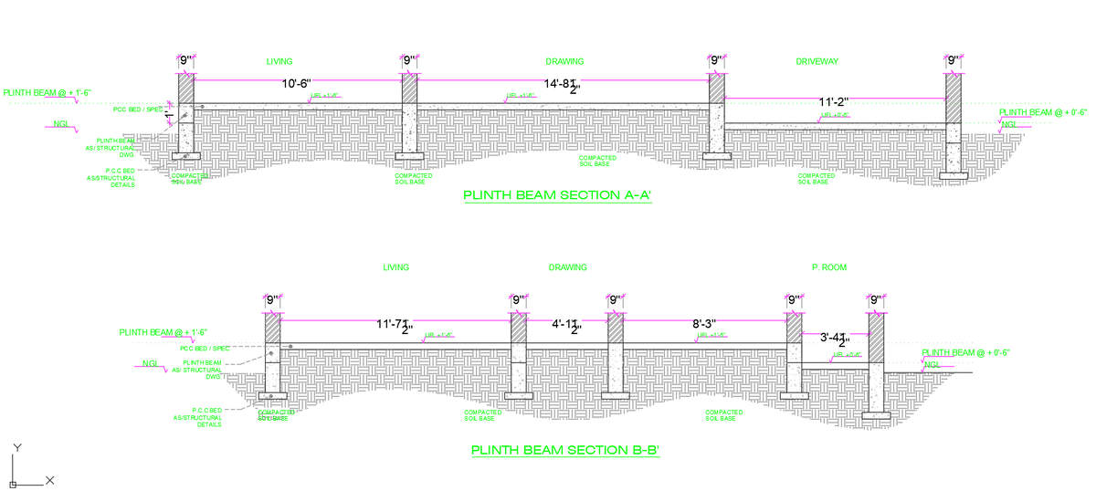
Plinth Beam Section Detail With 10 Feet 6 Inch and 14 Feet 8 Inch Span

Ratings & Reviews
Be the first to share your experience with this product. Your review helps others make better decisions!
Description
Plinth beam section detail drawing showing structural foundation beam sections with sectional views labelled Plinth Beam Section A A and Plinth Beam Section B B. The drawing presents detailed structural spacing between columns and walls, including spans of 10 feet 6 inches, 14 feet 8 inches, and 11 feet 2 inches across the living drawing and driveway areas. Additional sectional measurements include 11 feet 7 inches, 4 feet 1 inch, 8 feet 3 inches, and 3 feet 4 inches between structural supports as shown in the second section layout. The structural elements illustrate a 9-inch column and wall thickness with plinth beam levels indicated at plus 1 feet 6 inches and plus 0 feet 6 inches above NGL natural ground level. The drawing also includes construction layers such as PCC bed specification, compacted soil base, and plinth beam placement as per structural drawings. Room references, including the living drawing and P room, are identified along the beam alignment, showing how structural beams support the building layout. This plinth beam section detail AutoCAD DWG drawing provides clear construction references for foundation beam placement, column spacing, soil base preparation, and structural level alignment used in residential building construction.
Tags
Uploaded by:
john
kelly
Ratings & Reviews
Be the first to share your experience with this product. Your review helps others make better decisions!