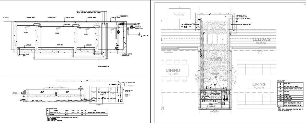
Piping Pond Installation DWG Ground Floor Pump Room Detail Plan
Ratings & Reviews
Be the first to share your experience with this product. Your review helps others make better decisions!
Description
A detailed Piping Pond Installation DWG Ground Floor Pump Room Detail Plan presenting a complete pond filtration system layout, pump room configuration, and single line diagram for accurate installation. The drawing includes multiple filtration chambers labeled Filter 1, Filter 2, and Filter 3 with internal plastic mesh layers, overflow pipes, bottom drain connections, and pipe routing layouts. The plan specifies pipe sizes such as 50 mm and 80 mm diameter lines, drainage slopes around 1 percent, and interconnection between chambers for efficient water circulation. The pump room detail shows equipment placement, including submersible pump units, UV clarifier, ball valves, check valves, and filtration control systems with clear piping directions. Ground floor pond layout indicates spatial integration near dining and living zones with finished floor levels such as FFL plus 1.250 and FFL plus 1.200 for terrace areas. Additional annotations include skimmer lines, return pipes, suction lines, and gutter capacity around 0.5 meters with drainage outlets. This Piping Pond Installation DWG Ground Floor Pump Room Detail Plan provides precise measurements, piping alignment, and system detailing suitable for architects and engineers.
Tags
Uploaded by:
Priyanka
Patel
Ratings & Reviews
Be the first to share your experience with this product. Your review helps others make better decisions!