Corporate Office HVAC Layout DWG Second Floor FCU DX Plan Design

Ratings & Reviews
Be the first to share your experience with this product. Your review helps others make better decisions!
Description
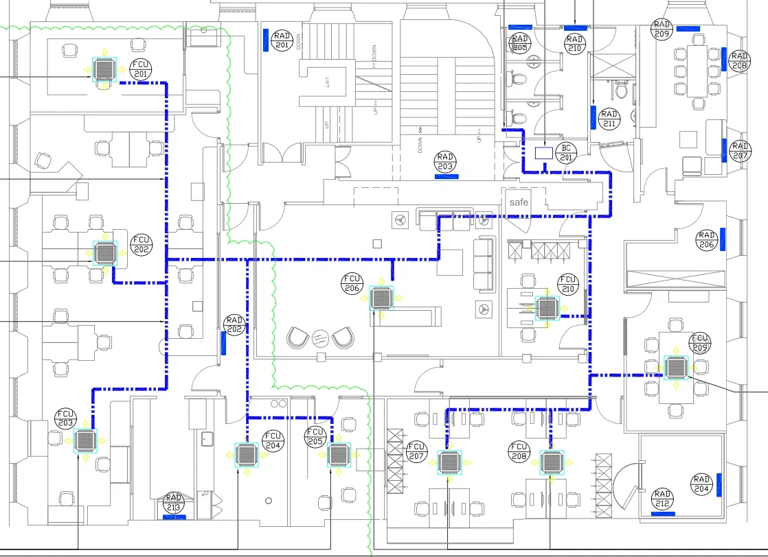
A comprehensive Corporate Office HVAC Layout DWG Second Floor FCU DX Plan presenting a detailed mechanical services drawing for a second-floor office environment. The layout clearly illustrates heating and cooling systems using 4-way blow cassette units mounted at high level within ceiling spaces, ensuring efficient air distribution. Multiple FCU units, such as FCU 201 to FCU 210, are strategically placed across office cabins, meeting rooms, open workspaces, and lounge areas, while radiator points RAD 201 to RAD 213 provide supplementary heating. The drawing includes a DX pipe routing layout with clearly defined service paths, showing connection to the branch circuit controller BC 201 located within the ceiling void, serving multiple floors. DX service lines TA and TB connect indoor units to outdoor units, ensuring system continuity. The plan also details cable tray routing, condensate drainage, electrical panel heaters, and coordination with architectural layouts. Notes specify installation standards, fire sealing requirements, insulation, and testing procedures for HVAC systems. The drawing is prepared at scale 1 to 50 and is suitable for execution, coordination, and tender documentation of the Corporate Office HVAC Layout DWG Second Floor FCU DX Plan.
Tags
Uploaded by:
john
kelly
Ratings & Reviews
Be the first to share your experience with this product. Your review helps others make better decisions!